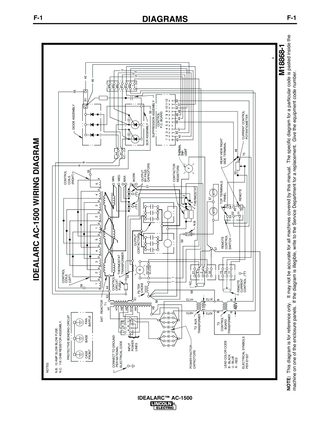
IDEALARC AC-1500 WIRING DIAGRAM


F-


NOTES:


1


N.B. 10 AMP SLOW BLOW FUSE.


N.C. 11K OHM RESISTOR ASSEMBLY.


CONTROL


CONTROL


PROTECTIVE BONDING CIRCUIT


COILS


(LEFT)


COILS


(RIGHT)


DIODE ASSEMBLY

56


56


B

B


R1

45


CASE

BASE


FAN


55


FRONT


BAFFLE


48


1


2 FS

3 FS

4

FS 5


1 FS

2 FS

3 FS

4 FS

5


SAT. REACTOR

S

FS

FS

F


H1 T1

X2

44


44


CONNECT TO GROUND


H7


CONTROL


MIN.

44


43


PER NATIONAL


CIRCUIT

THERMOSTAT


MED.


42


ELECTRICAL CODE

{

7

9 10


H8


FUSE


41


41


U


TRANSFORMER


MAX.


4

8 1


H9


59


X1


INPUT


X2


H10


POWER


X1


OUTPUT


WORK


1


U


H4


U

U


LINES


FILTER


IDEALARC™ AC-1500


R


CONTACTORS


CHOKE


OUTPUT


DIAGRAMS


FUSE


21


BY-PASS


SCR ASSEMBLY


CAPACITORS


55


H5 58


SUPPRESSION ASSEMBLY


CONTROL


P.C. BOARD


1

2

3

4

5

6

7

8


9 10 1112


1

1


CONTACTOR

43


45


46


48


X2


52


RESISTORS


42

41


44

49

X1


58


1

2


THERMAL


TRIP


POWER FACTOR


H2T2


H1T2


FUSE


Y

LIGHT


58

N.C.


21


3


CAPACITORS


T2 AUX.


N.B.


THERMOSTAT


TRANSFORMER


4


2


115V


X2T2


31


X1T2


32


MTR

57

MTR


57


B


T3


B


75


TOP TERMINALS

REAR VIEW RIGHT


CONTROL


REMOTE


LEAD COLOR CODE


BOARD


76


CONTROL


PANEL


SIDE TERMINAL


B - BLACK


TRANSFORMER

R


R


77


SWITCH


53

52

54


U - BLUE


48V


46


53

49


R - RED


REMOTE


77

REMOTE


76


ELECTRICAL SYMBOLS


CURRENT


75

CURRENT CONTROL


CONTROL


PER E1537


POTENTIOMETER


B


M18868-1

NOTE: This diagram is for reference only. It may not be accurate for all machines covered by this manual. The specific diagram for a particular code is pasted inside the

F

machine on one of the enclosure panels. If the diagram is illegible, write to the Service Department for a replacement. Give the equipment code number.

-1

Page 20
Image 20
Lincoln Electric manual Diagrams, Idealarc AC-1500 Wiring Diagram

AC-1500 specifications

The Lincoln Electric AC-1500 is a versatile and innovative arc welding machine that has garnered attention for its reliability and performance in various industrial applications. Designed to provide powerful welding capabilities, the AC-1500 is particularly beneficial for both professionals and hobbyists who require a robust and efficient welding solution.

One of the standout features of the Lincoln Electric AC-1500 is its capability to produce alternating current (AC) welding. This technology is ideal for welding a variety of materials, including aluminum and magnesium, which can be challenging with conventional direct current (DC) welders. The AC output allows for a smooth arc and a stable weld process, resulting in high-quality welds and minimal spatter.

The AC-1500 is equipped with a user-friendly control panel that simplifies the welding process. It offers adjustable amperage settings, enabling users to fine-tune the output to match specific materials and thicknesses. This versatility ensures excellent penetration and control over the welding process, making it suitable for various projects, from automotive repairs to constructing metal fabrications.

Another key characteristic of the AC-1500 is its portability. Weighing in at a manageable level, it features built-in handles that facilitate easy transportation between job sites. This design is particularly advantageous for welders who often move their equipment, providing convenience without sacrificing performance.

Durability is a hallmark of the Lincoln Electric AC-1500. The machine is built with high-quality materials that withstand the rigors of industrial environments. Its robust construction ensures a long service life, reducing the need for frequent repairs or replacements. Additionally, the AC-1500 is designed with safety features, including thermal overload protection that prevents overheating, ensuring that the welder can work efficiently without concern for equipment malfunction.

In terms of technologies, the AC-1500 incorporates advanced circuits that enhance the stability of the arc, even in difficult welding positions. This technology is critical in achieving consistent results, particularly when welding in challenging conditions.

In conclusion, the Lincoln Electric AC-1500 is a powerful, reliable, and user-friendly arc welding machine. Its AC welding capabilities, adjustable amperage, portability, and robust design make it an excellent choice for a wide range of welding applications. Whether used in a professional setting or by enthusiastic DIY welders, the AC-1500 delivers superior performance that meets the demands of modern welding tasks.