INSTALLATION
When connecting the Control Module to a
CAUTION: Be sure that mode switch is in correct position before attempting to operate control module. Incorrect switch position could result in damage to the control module and/or power source. Cunsult your power source instruction manual to see what type of output contactor circuit it has. Be sure to reinstall lockout bar if switch position is altered.
Connection to 487-25 Spool Gun
Connect the electrode cable, gas line, and control cable of the spool gun to their respective connectors on the front of the Control Module.
Connection to 469-25 Spool Gun*
1.Connect K518 adapter to spool gun control cable.
2.Connect the electrode cable, gas line, and control cable of the spool gun to their respective connectors on the front of the Control Module.
*Requires K518 adapter (ordered separately)
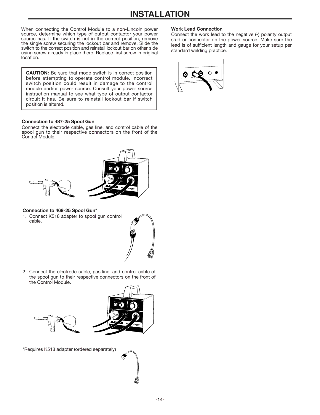
Work Lead Connection
Connect the work lead to the negative
