IM573 specifications
The Lincoln Electric IM573 is a state-of-the-art welding machine that has garnered attention for its advanced features and cutting-edge technologies. Designed to meet the demands of both industrial and commercial applications, the IM573 combines reliability with versatility.One of the main features of the IM573 is its robust arc performance. The machine is equipped with Lincoln Electric's proprietary Arc Control technology, which enhances the stability of the arc for smooth and consistent welds in a variety of materials. This feature is particularly beneficial for operators who need to work with thin gauge metals, as it minimizes burn-through and ensures precise weld penetration.
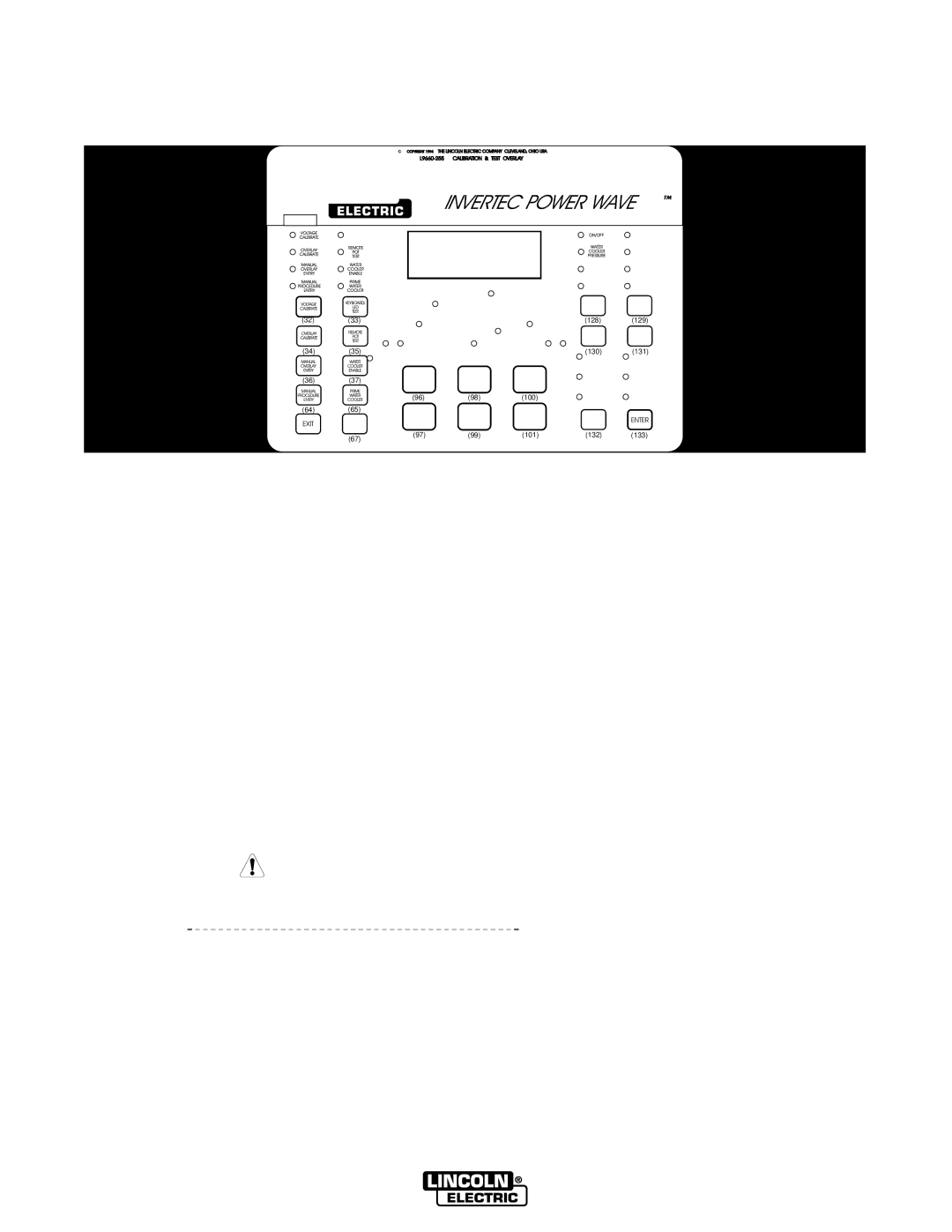
The IM573 boasts a digital display interface, providing users with real-time data on welding parameters. This intuitive interface allows for easy adjustments and monitoring of voltage, amperage, and wire feed speed, enabling operators to tailor their settings to suit specific welding tasks. Additionally, the machine includes pre-set programs for various welding processes, making it easier for users to select the optimal settings for common applications.
Versatility is another hallmark of the IM573. It supports multiple welding processes, including MIG, TIG, and Stick welding. This multi-process functionality enables users to switch between techniques quickly, making it a valuable asset in environments where different welding methods are required. The ability to weld a wide range of materials, from carbon steel to stainless steel and aluminum, further enhances the machine's appeal.
In terms of build quality, the IM573 is designed for durability and longevity. It features a rugged housing and temperature protection to withstand demanding work environments. The machine is also designed for easy maintenance, with accessible components that simplify troubleshooting and repair.
Safety is a priority in the design of the IM573. It includes features such as overload protection and thermal overload shutdown, ensuring that the machine operates within safe parameters. This not only protects the equipment but also enhances the safety of the operator.
In summary, the Lincoln Electric IM573 is an advanced welding machine that combines superior arc performance, user-friendly digital controls, and versatile welding capabilities. Its durable construction and safety features make it an excellent choice for professionals seeking a reliable solution for their welding needs. Whether in a workshop or on a job site, the IM573 stands out as a top-tier option in the welding machinery market.

