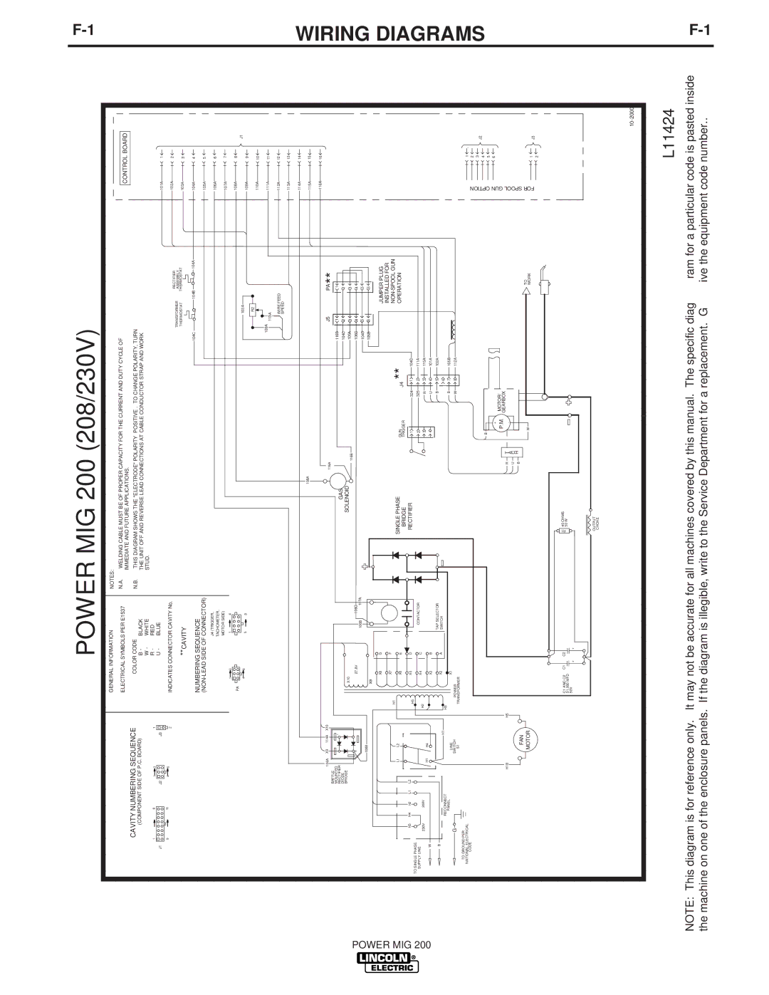
POWER MIG 200 (208/230V)


GENERAL INFORMATION


NOTES:


ELECTRICAL SYMBOLS PER E1537


N.A.

WELDING CABLE MUST BE OF PROPER CAPACITY FOR THE CURRENT AND DUTY CYCLE OF


CONTROL BOARD


IMMEDIATE AND FUTURE APPLICATIONS.


CAVITY NUMBERING SEQUENCE


COLOR CODE


N.B.

THIS DIAGRAM SHOWS THE "ELECTRODE" POLARITY “POSITIVE”. TO CHANGE POLARITY, TURN


(COMPONENT SIDE OF P.C. BOARD)


B -

BLACK


THE UNIT OFF AND REVERSE LEAD CONNECTIONS AT CABLE CONDUCTOR STRAP AND WORK


W -

WHITE


STUD.


1


8


1

3


1


R -

RED


J1


J2


J3


U -

BLUE


101A

1


9


16


4

6


2


INDICATES CONNECTOR CAVITY No.


102A

2


TRANSFORMER

RECTIFIER


** CAVITY


ASSEMBLY


THERMOSTAT

THERMOSTAT

103A

3


NUMBERING SEQUENCE


104C

104B

104A

104A

4


(NON-LEAD SIDE OF CONNECTOR)


105A

5


J4 (TRIGGER,


106A

6


TACHOMETER,


MOTOR SIDE)


107A

7


1

3


1

4


PA


108A

8


J1


4

6


103A


5

8


109A

9


R2


110A

10


109A


111A

11


113A


WIRE FEED


112A

12


SPEED


113A

13


114A

14


108A


115A

15


116A

16


106A

X9

114A

X10


116A


J5

PA


BAFFLE


1 **


MOUNTED


-


116B

1


RECTIFIER


GAS


DIODE


104C

2

2


BRIDGE


X10


SOLENOID


105A


POWER


116B


3

3


+


106C


106C

INSTALLED FOR


27.8V


4

4


106B

107A


104D

5

5


106B


105B

6

6


X9


X8


G


JUMPER PLUG


MIG


H1

X7


F


NON-SPOOL GUN


H3

H4

H2

L1

L2


X5


D


RECTIFIER


1


L1


L2


X6


E


SINGLE PHASE


GUN


J4

**


OPERATION


BRIDGE


TRIGGER


200

TO SINGLE PHASE


H5


1

324


104D


X3


B


4

U


4

101A


W


SUPPLY LINE


X4


C

CONTACTOR


2

325


2

111A


230V


208V


H2


3

R


3

115A


H1


H4


B


X2


A

TAP SELECTOR


B


5

102A


SWITCH


RECONNECT


H1


6


H3


PANEL


LINE


X1


B


7

105B


G


SWITCH


POWER


W


8

112A


S1


TRANSFORMER


TO GROUND PER


NATIONAL ELECTRICAL


1


CODE


OPTION

5


2


3

J2


4


B


+


GUN

6


P.M.

MOTOR/


GEARBOX


H1B


H5


R

T

-


SPOOL


A


U

C


FAN


B

H


TO


FOR

1

J3


MOTOR


W


WORK


2


C1 AND C2

C1

C2


R1 40 OHMS


31,000 MFD


50 W


50V

+

+


OUTPUT


CHOKE


10- 2000

L11424

NOTE: This diagram is for reference only. It may not be accurate for all machines covered by this manual. The specific diagram for a particular code is pasted inside the machine on one of the enclosure panels. If the diagram is illegible, write to the Service Department for a replacement. Give the equipment code number..

F-1

WIRING DIAGRAMS

F-1

Page 27
Image 27
Lincoln Electric IM693 manual Power MIG 200 208/230V

IM693 specifications

Lincoln Electric IM693 is a cutting-edge multiprocess welding machine designed to cater to the needs of both industrial and commercial applications. Renowned for its versatility, this machine can perform MIG, TIG, and stick welding, making it an ideal choice for fabricators and manufacturers looking for a single solution for varied welding processes.

One of the standout features of the IM693 is its advanced inverter technology. This technology significantly enhances the efficiency of the welding process by reducing energy consumption while maximizing output. The inverter design allows for a more compact and lightweight unit compared to traditional transformers, making it easier to transport and maneuver in work environments.

The machine’s user-friendly interface is another compelling characteristic. It is equipped with a large, intuitive digital display that allows operators to quickly adjust settings for specific applications. The system is designed to provide real-time feedback on welding parameters, ensuring consistent and high-quality welds. This feature is particularly beneficial for both novice and experienced welders, facilitating a smoother workflow.

Additionally, Lincoln Electric IM693 incorporates advanced arc control technologies such as Soft Start and Auto Set features. Soft Start allows for a gradual ramp-up of the welding current, which minimizes spatter and leads to cleaner welds. The Auto Set feature intelligently adjusts the welder's settings based on the material type and thickness, taking the guesswork out of the welding process and improving overall efficiency.

The IM693 supports a wide range of input voltages, allowing for operation in various regions without the need for additional equipment. This flexibility makes it suitable for numerous applications, ranging from automotive repair to heavy machinery fabrication.

Safety is paramount in industrial settings, and the Lincoln Electric IM693 does not compromise on this front. It is equipped with several safety features such as thermal overload protection, which prevents machine damage from overheating, and a sturdy casing that protects vital components from dust and debris.

In summary, Lincoln Electric IM693 is a robust, versatile, and technologically advanced welding machine that meets the demands of modern welding applications. Its combination of inverter technology, user-friendly features, and safety measures makes it an excellent choice for professionals looking to achieve high-quality results with maximum efficiency.