CAUTION
NOTE: DO NOT ADD MORE THAN 2 GALLONS (7.6 LITERS) OF COOLANT INTO THE RESER- VOIR. The fill cap contains a pressure release air hole, which must not be blocked by overfilling the reservoir with coolant.
------------------------------------------------------------------------
Be certain to replace the reservoir fill cap when the reservoir is full. Simply press on the inside center of the fill cap until the cap snaps into place. Operation of the cooler without the fill cap in place can cause poor cooling efficiency, evaporation loss of coolant and reduced product life.
COOLANT CONNECTIONS
The fittings located on the back center of the cooler drawer are two female 5/8-18 left-hand threaded fit- tings (CGA Style). The hoses provided with this unit are color coded with red (hot) and blue (cold) tape that should be matched up with the decals, also color coded, on both the cooler and the TIG machine. Recommended torque value for the 5/8-18 LH fittings is 12 – 15 ft lbs. If a torque wrench is not available, snug the fittings and check for leaks.
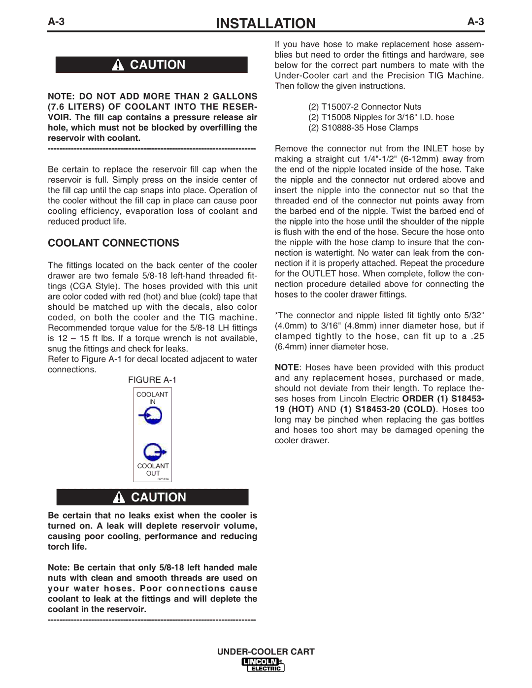
Refer to Figure A-1 for decal located adjacent to water connections.
FIGURE A-1
COOLANT
IN
COOLANT
OUT
S25134
 CAUTION
Be certain that no leaks exist when the cooler is turned on. A leak will deplete reservoir volume, causing poor cooling, performance and reducing torch life.
Note: Be certain that only 5/8-18 left handed male nuts with clean and smooth threads are used on your water hoses. Poor connections cause coolant to leak at the fittings and will deplete the coolant in the reservoir.
------------------------------------------------------------------------
If you have hose to make replacement hose assem- blies but need to order the fittings and hardware, see below for the correct part numbers to mate with the Under-Cooler cart and the Precision TIG Machine. Then follow the given instructions.
(2) T15007-2 Connector Nuts
(2)T15008 Nipples for 3/16" I.D. hose
(2)S10888-35 Hose Clamps
Remove the connector nut from the INLET hose by making a straight cut 1/4"-1/2" (6-12mm) away from the end of the nipple located inside of the hose. Take the nipple and the connector nut ordered above and insert the nipple into the connector nut so that the threaded end of the connector nut points away from the barbed end of the nipple. Twist the barbed end of the nipple into the hose until the shoulder of the nipple is flush with the end of the hose. Secure the hose onto the nipple with the hose clamp to insure that the con- nection is watertight. No water can leak from the con- nection if it is properly attached. Repeat the procedure for the OUTLET hose. When complete, follow the con- nection procedure detailed above for connecting the hoses to the cooler drawer fittings.
*The connector and nipple listed fit tightly onto 5/32" (4.0mm) to 3/16" (4.8mm) inner diameter hose, but if clamped tightly to the hose, can fit up to a .25 (6.4mm) inner diameter hose.
NOTE: Hoses have been provided with this product and any replacement hoses, purchased or made, should not deviate from their length. To replace the- ses hoses from Lincoln Electric ORDER (1) S18453-
19(HOT) AND (1) S18453-20 (COLD). Hoses too long may be pinched when replacing the gas bottles and hoses too short may be damaged opening the cooler drawer.