SP-135 PLUS

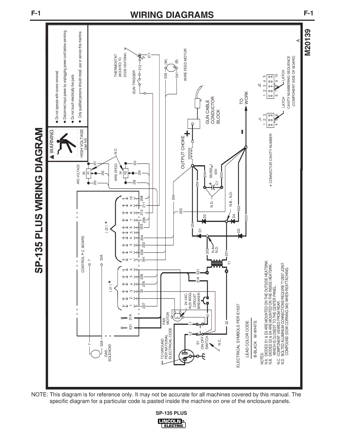
specific diagram for a particular code is pasted inside the

NOTE: This diagram is for reference only. It may not be accurate


machine on one

for all machines


of the enclosure panels.

covered by this manual.


The

WARNING

ARC VOLTAGE


CONTROL P.C. BOARD


5K

HIGH VOLTAGE


can kill

7


7


R1


205

207


32A


32A


206


GAS


( J2 )


SOLENOID


( J1 )


WIRE SPEED

N.C.


5K


R2


531

31A

1

2

3

4

5

6

1

2

3

4

5

6

7


8

9

10


208

203


32

205 206

541 539 203 204


203


213

211 208

209


207


209


TO GROUND

FAN


PER NATIONAL


MOTOR


ELECTRICAL CODE


204


203


OUTPUT CHOKE


24 VAC


L2

L1


AUX WDG.


204


CIRCUIT


S1


31A

531


204


BREAKER


D1


ON-OFF


D2


A

204


SWITCH


31


202


+

59,000 u f


N.A.


N.D.


40V


N.C.


N.D.


C1


A

203


32


T1

201


N.B., N.D.


D4


ELECTRICAL SYMBOLS PER E1537


D3


203


LEAD COLOR CODE:


203


B-BLACK W-WHITE


NOTES:


N.A. DIODES D1 & D3 ARE MOUNTED ON THE OUTSIDE HEATSINK.


N.B. DIODES D2 & D4 ARE MOUNTED ON THE INSIDE HEATSINK,


*CONNECTOR CAVITY NUMBER

WHICH IS CLOSEST TO THE CENTER PANEL.


N.C. COMPONENT VIEWED FROM REAR.

N.D. BOLTED ALUMINUM CONNECTIONS REQUIRE T12837 JOINT

COMPOUND (DOW CORNING 340) WHEN REATTACHING.

Do not operate with covers removed.

Disconnect input power by unplugging power cord before servicing.

Do not touch electrically live parts

Only qualified persons should install, use or service this machine.

THERMOSTAT

(MOUNTED TO

DIODE HEATSINK)

GUN TRIGGER

212

A


211

539 (W)

541 + (B)

WIRE FEED MOTOR

GUN CABLE

CONDUCTOR

BLOCK

TO

WORK


J1


J2


1

2

3

1

2

3

4

5

4

5

6

6

7

8

9

10

LATCH LATCH

CAVITY NUMBERING SEQUENCE (COMPONENT SIDE OF BOARD)

A

M20139

F-1

WIRING DIAGRAMS

F-1

Page 32
Image 32
Lincoln Electric IM788 manual Wiring Diagrams, High Voltage

IM788 specifications

The Lincoln Electric IM788 is a cutting-edge industrial welding inverter known for its advanced features and technologies that enhance productivity and efficiency in various welding applications. This machine is specifically designed to cater to the demands of high-performance environments while maintaining reliability and ease of use.

One of the standout features of the IM788 is its multi-process capability. It offers MIG, TIG, and stick welding options, making it a versatile choice for welders who work with a diverse range of materials and thicknesses. This flexibility enables operators to switch processes seamlessly without compromising on performance, thereby increasing overall productivity.

The IM788 is equipped with Lincoln Electric's exclusive Synchronized Arc Control Technology, which optimizes the arc characteristic for different materials and welding conditions. This technology helps to achieve cleaner and more precise welds, minimizing the need for post-weld finishing. Additionally, the machine offers a broad range of voltage and amperage settings, allowing for fine-tuning based on specific project requirements.

Another significant attribute of the IM788 is its built-in intelligence. The machine incorporates advanced microprocessor control, which enhances user interface capabilities and allows for easy adjustments to welding parameters. The intuitive digital display provides real-time feedback on settings and performance, enabling operators to make informed decisions and adjustments as needed.

Durability is also a key characteristic of the Lincoln Electric IM788. Its hardened metal case ensures protection against harsh working conditions, while internal components are designed to withstand heavy usage. This robust construction not only extends the machine's lifespan but also maintains consistent performance even in demanding environments.

The IM788's compact design and lightweight construction make it portable and easy to transport, allowing welders to move it effortlessly between job sites. Coupled with its energy-efficient operation, this inverter contributes to lower operational costs, making it an economical investment for both small workshops and large industrial operations.

In summary, the Lincoln Electric IM788 stands out for its multi-process capabilities, advanced welding technologies, user-friendly interface, and robust design. These features make it an ideal choice for professionals seeking a reliable and efficient welding solution. Whether for fabrication shops, construction sites, or maintenance applications, the IM788 delivers exceptional performance and versatility, solidifying its position as a leading welding inverter in the market.