SP-135 PLUS

B-4

OPERATION

B-4

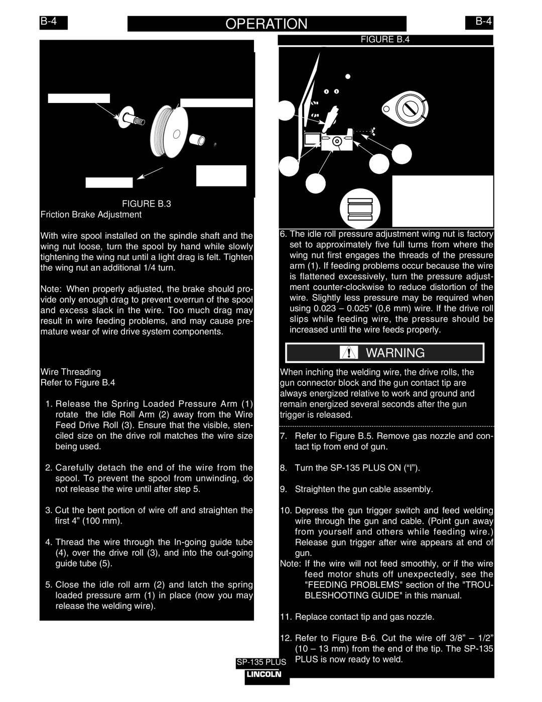
Wire Spindle Shaft

4" Wire Spool


Wing Nut

To wire drive

and Spacer


FIGURE B.3

Friction Brake Adjustment

With wire spool installed on the spindle shaft and the wing nut loose, turn the spool by hand while slowly tightening the wing nut until a light drag is felt. Tighten the wing nut an additional 1/4 turn.

Note: When properly adjusted, the brake should pro- vide only enough drag to prevent overrun of the spool and excess slack in the wire. Too much drag may result in wire feeding problems, and may cause pre- mature wear of wire drive system components.

Wire Threading

Refer to Figure B.4

1.Release the Spring Loaded Pressure Arm (1) rotate the Idle Roll Arm (2) away from the Wire Feed Drive Roll (3). Ensure that the visible, sten- ciled size on the drive roll matches the wire size being used.

2.Carefully detach the end of the wire from the spool. To prevent the spool from unwinding, do not release the wire until after step 5.

3.Cut the bent portion of wire off and straighten the first 4” (100 mm).

4.Thread the wire through the In-going guide tube (4), over the drive roll (3), and into the out-going guide tube (5).

5.Close the idle roll arm (2) and latch the spring loaded pressure arm (1) in place (now you may release the welding wire).

FIGURE B.4

2

5

1

4

3

The Wire Drive Feed

Roll can accommodate


two wire sizes by flipping


the wire drive feed roll


over. The sizes are sten-


ciled on the drive roll.

6.The idle roll pressure adjustment wing nut is factory set to approximately five full turns from where the wing nut first engages the threads of the pressure arm (1). If feeding problems occur because the wire is flattened excessively, turn the pressure adjust- ment counter-clockwise to reduce distortion of the wire. Slightly less pressure may be required when using 0.023 – 0.025" (0,6 mm) wire. If the drive roll slips while feeding wire, the pressure should be increased until the wire feeds properly.

WARNING

When inching the welding wire, the drive rolls, the gun connector block and the gun contact tip are always energized relative to work and ground and remain energized several seconds after the gun trigger is released.

7.Refer to Figure B.5. Remove gas nozzle and con- tact tip from end of gun.

8.Turn the SP-135 PLUS ON (“I”).

9.Straighten the gun cable assembly.

10.Depress the gun trigger switch and feed welding wire through the gun and cable. (Point gun away from yourself and others while feeding wire.) Release gun trigger after wire appears at end of gun.

Note: If the wire will not feed smoothly, or if the wire feed motor shuts off unexpectedly, see the "FEEDING PROBLEMS" section of the "TROU- BLESHOOTING GUIDE" in this manual.

11.Replace contact tip and gas nozzle.

12.Refer to Figure B-6. Cut the wire off 3/8” – 1/2” (10 – 13 mm) from the end of the tip. The SP-135 PLUS is now ready to weld.

Page 17
Image 17
Lincoln Electric IM788 manual Friction Brake Adjustment, Wire Threading

IM788 specifications

The Lincoln Electric IM788 is a cutting-edge industrial welding inverter known for its advanced features and technologies that enhance productivity and efficiency in various welding applications. This machine is specifically designed to cater to the demands of high-performance environments while maintaining reliability and ease of use.

One of the standout features of the IM788 is its multi-process capability. It offers MIG, TIG, and stick welding options, making it a versatile choice for welders who work with a diverse range of materials and thicknesses. This flexibility enables operators to switch processes seamlessly without compromising on performance, thereby increasing overall productivity.

The IM788 is equipped with Lincoln Electric's exclusive Synchronized Arc Control Technology, which optimizes the arc characteristic for different materials and welding conditions. This technology helps to achieve cleaner and more precise welds, minimizing the need for post-weld finishing. Additionally, the machine offers a broad range of voltage and amperage settings, allowing for fine-tuning based on specific project requirements.

Another significant attribute of the IM788 is its built-in intelligence. The machine incorporates advanced microprocessor control, which enhances user interface capabilities and allows for easy adjustments to welding parameters. The intuitive digital display provides real-time feedback on settings and performance, enabling operators to make informed decisions and adjustments as needed.

Durability is also a key characteristic of the Lincoln Electric IM788. Its hardened metal case ensures protection against harsh working conditions, while internal components are designed to withstand heavy usage. This robust construction not only extends the machine's lifespan but also maintains consistent performance even in demanding environments.

The IM788's compact design and lightweight construction make it portable and easy to transport, allowing welders to move it effortlessly between job sites. Coupled with its energy-efficient operation, this inverter contributes to lower operational costs, making it an economical investment for both small workshops and large industrial operations.

In summary, the Lincoln Electric IM788 stands out for its multi-process capabilities, advanced welding technologies, user-friendly interface, and robust design. These features make it an ideal choice for professionals seeking a reliable and efficient welding solution. Whether for fabrication shops, construction sites, or maintenance applications, the IM788 delivers exceptional performance and versatility, solidifying its position as a leading welding inverter in the market.