INSTALLATION | ||
|
|
|
c.For
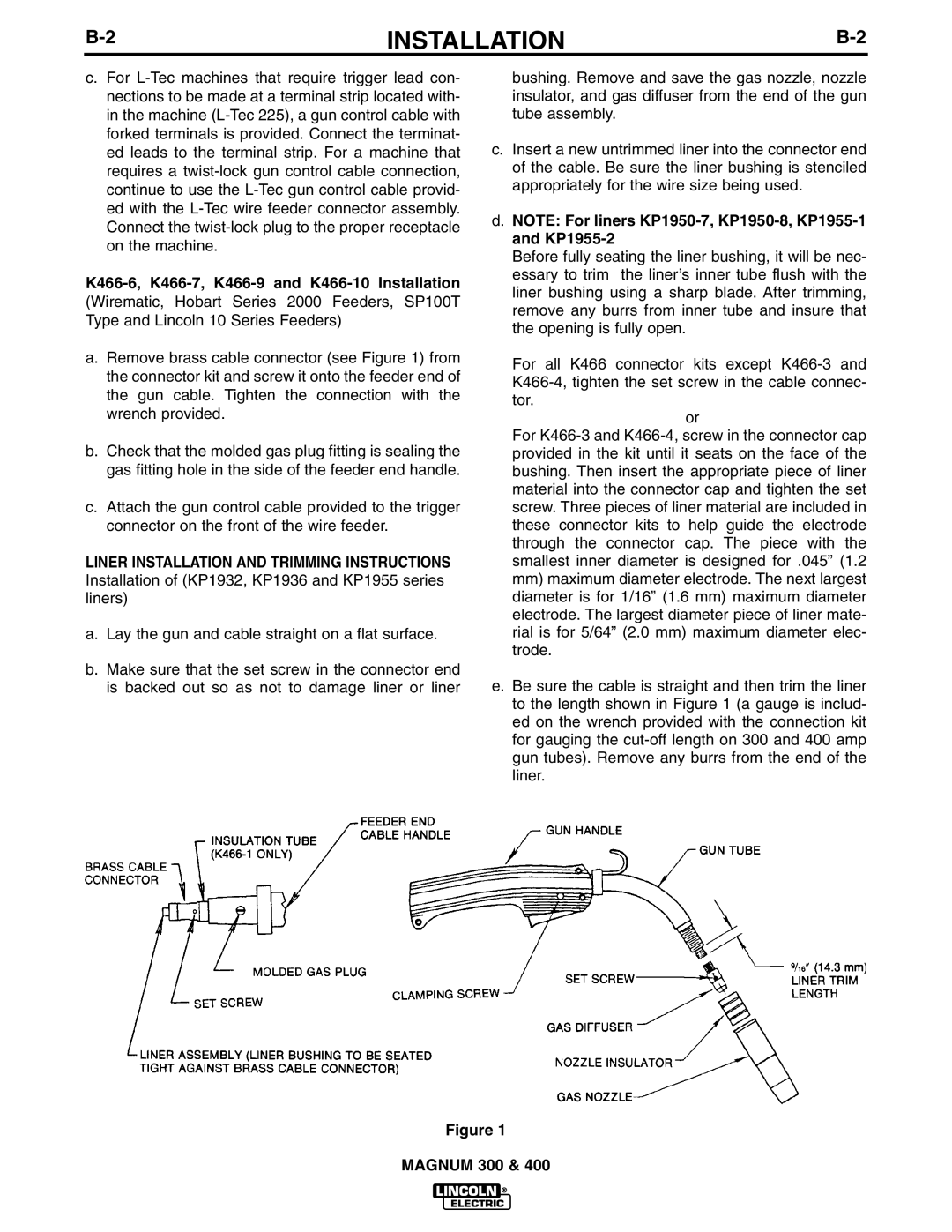
a.Remove brass cable connector (see Figure 1) from the connector kit and screw it onto the feeder end of the gun cable. Tighten the connection with the wrench provided.
b.Check that the molded gas plug fitting is sealing the gas fitting hole in the side of the feeder end handle.
c.Attach the gun control cable provided to the trigger connector on the front of the wire feeder.
LINER INSTALLATION AND TRIMMING INSTRUCTIONS Installation of (KP1932, KP1936 and KP1955 series liners)
a.Lay the gun and cable straight on a flat surface.
b.Make sure that the set screw in the connector end is backed out so as not to damage liner or liner
bushing. Remove and save the gas nozzle, nozzle insulator, and gas diffuser from the end of the gun tube assembly.
c.Insert a new untrimmed liner into the connector end of the cable. Be sure the liner bushing is stenciled appropriately for the wire size being used.
d.NOTE: For liners
Before fully seating the liner bushing, it will be nec- essary to trim the liner’s inner tube flush with the liner bushing using a sharp blade. After trimming, remove any burrs from inner tube and insure that the opening is fully open.
For all K466 connector kits except
or
For
mm) maximum diameter electrode. The next largest diameter is for 1/16” (1.6 mm) maximum diameter electrode. The largest diameter piece of liner mate- rial is for 5/64” (2.0 mm) maximum diameter elec- trode.
e.Be sure the cable is straight and then trim the liner to the length shown in Figure 1 (a gauge is includ- ed on the wrench provided with the connection kit for gauging the
Figure 1
MAGNUM 300 & 400