TROUBLESHOOTING | ||
|
|
|
TROUBLESHOOTING
PROCEDURES
A. PROCEDURE FOR REPLACING PC BOARDS
When a PC board is to be replaced, the following procedure must be followed:
1.Visually inspect PC board in question. Are any of the components damaged? Is a conductor on the back side of the board damaged?
a.If there is no damage to the PC board, insert a new one and see if this remedies the prob- lem. If the problem is remedied replace the old PC board and see if the problem still exists with the old PC board.
1.If the problem does not exist with the old board, check the PC board harness plug and PC board plug for corrosion, contam- ination, or oversize.
2.Check leads in the harness for loose con- nections.
b.If there is damage to the PC board, refer to the Troubleshooting Guide.
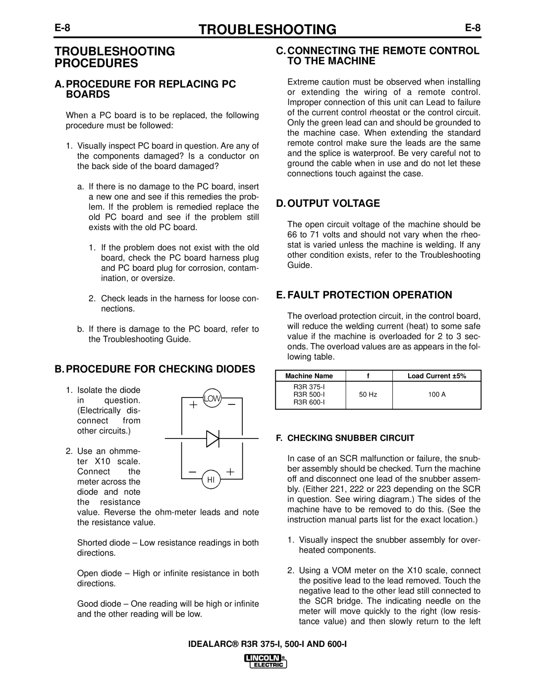
B.PROCEDURE FOR CHECKING DIODES
1.Isolate the diode
in question. (Electrically dis- connect from other circuits.)
2.Use an ohmme- ter X10 scale.
Connect the meter across the diode and note the resistance
value. Reverse the
Shorted diode – Low resistance readings in both directions.
Open diode – High or infinite resistance in both directions.
Good diode – One reading will be high or infinite and the other reading will be low.
C. CONNECTING THE REMOTE CONTROL TO THE MACHINE
Extreme caution must be observed when installing or extending the wiring of a remote control. Improper connection of this unit can Lead to failure of the current control rheostat or the control circuit. Only the green lead can and should be grounded to the machine case. When extending the standard remote control make sure the leads are the same and the splice is waterproof. Be very careful not to ground the cable when in use and do not let these connections touch against the case.
D. OUTPUT VOLTAGE
The open circuit voltage of the machine should be 66 to 71 volts and should not vary when the rheo- stat is varied unless the machine is welding. If any other condition exists, refer to the Troubleshooting Guide.
E. FAULT PROTECTION OPERATION
The overload protection circuit, in the control board, will reduce the welding current (heat) to some safe value if the machine is overloaded for 2 to 3 sec- onds. The overload values are as appears in the fol- lowing table.
Machine Name | f | Load Current ±5% |
|
|
|
R3R |
|
|
R3R | 50 Hz | 100 A |
R3R |
|
|
|
|
|
F.CHECKING SNUBBER CIRCUIT
In case of an SCR malfunction or failure, the snub- ber assembly should be checked. Turn the machine off and disconnect one lead of the snubber assem- bly. (Either 221, 222 or 223 depending on the SCR in question. See wiring diagram.) The sides of the machine have to be removed to do this. (See the instruction manual parts list for the exact location.)
1.Visually inspect the snubber assembly for over- heated components.
2.Using a VOM meter on the X10 scale, connect the positive lead to the lead removed. Touch the negative lead to the other lead still connected to the SCR bridge. The indicating needle on the meter will move quickly to the right (low resis- tance value) and then slowly return to the left
IDEALARC® R3R