Return to Section TOC

TOC

Return to Master TOC

TOC

F-32F-32

TROUBLESHOOTING & REPAIR

CONTROL BOARD TEST (Continued)

J2


J5


J6


J7

J1


J8


J4

J3


Firing Board


Control Board

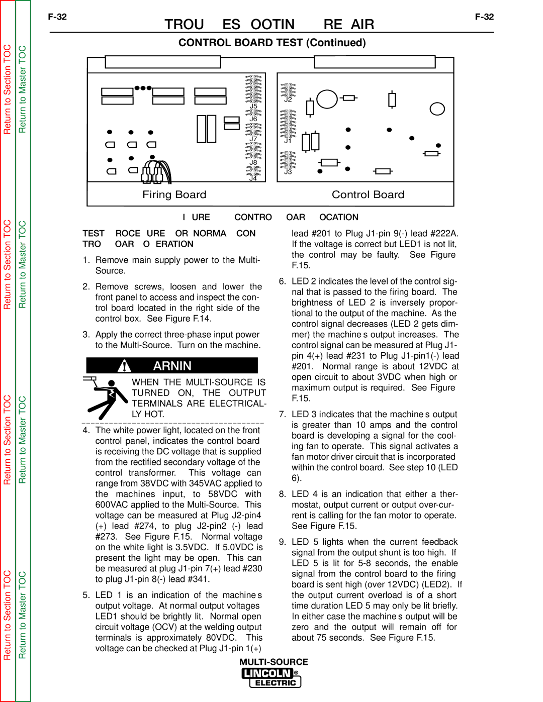
FIGURE F.14. CONTROL BOARD LOCATION

Return to Section

Return to Section TOC

Return to Section TOC

Return to Master

Return to Master TOC

Return to Master TOC

TEST PROCEDURE FOR NORMAL CON- TROL BOARD OPERATION

1.Remove main supply power to the Multi- Source.

2.Remove screws, loosen and lower the front panel to access and inspect the con- trol board located in the right side of the control box. See Figure F.14.

3.Apply the correct three-phase input power to the Multi-Source. Turn on the machine.

WARNING

WHEN THE MULTI-SOURCE IS

TURNED ON, THE OUTPUT

TERMINALS ARE ELECTRICAL-

LY HOT.

4.The white power light, located on the front control panel, indicates the control board is receiving the DC voltage that is supplied from the rectified secondary voltage of the control transformer. This voltage can range from 38VDC with 345VAC applied to the machines input, to 58VDC with 600VAC applied to the Multi-Source. This voltage can be measured at Plug J2-pin4

(+)lead #274, to plug J2-pin2 (-) lead #273. See Figure F.15. Normal voltage on the white light is 3.5VDC. If 5.0VDC is present the light may be open. This can be measured at plug J1-pin 7(+) lead #230 to plug J1-pin 8(-) lead #341.

5.LED 1 is an indication of the machine’s output voltage. At normal output voltages LED1 should be brightly lit. Normal open circuit voltage (OCV) at the welding output terminals is approximately 80VDC. This voltage can be checked at Plug J1-pin 1(+)

lead #201 to Plug J1-pin 9(-) lead #222A. If the voltage is correct but LED1 is not lit, the control may be faulty. See Figure

F.15.

6.LED 2 indicates the level of the control sig- nal that is passed to the firing board. The brightness of LED 2 is inversely propor- tional to the output of the machine. As the control signal decreases (LED 2 gets dim- mer) the machine’s output increases. The control signal can be measured at Plug J1- pin 4(+) lead #231 to Plug J1-pin1(-) lead #201. Normal range is about 12VDC at open circuit to about 3VDC when high or maximum output is required. See Figure

F.15.

7.LED 3 indicates that the machine’s output is greater than 10 amps and the control board is developing a signal for the cool- ing fan to operate. This signal activates a fan motor driver circuit that is incorporated within the control board. See step 10 (LED 6).

8.LED 4 is an indication that either a ther- mostat, output current or output over-cur- rent is calling for the fan motor to operate.

See Figure F.15.

9.LED 5 lights when the current feedback signal from the output shunt is too high. If LED 5 is lit for 5-8 seconds, the enable signal from the control board to the firing board is sent high (over 12VDC) (LED2). If the output current overload is of a short time duration LED 5 may only be lit briefly. In either case the machine’s output will be zero and the output will remain off for about 75 seconds. See Figure F.15.

MULTI-SOURCE

Page 60
Image 60
Lincoln Electric SVM155-A service manual Control Board Test, See Figure F.15

SVM155-A specifications

The Lincoln Electric SVM155-A is a state-of-the-art welding machine that excels in versatility and performance, making it ideal for both professional welders and hobbyists. This multi-process welder supports MIG, TIG, and stick welding processes, allowing users to tackle a wide range of applications with a single device. Its user-friendly design and advanced technology make it an exceptional choice for those looking to enhance their welding capabilities.

One of the main features of the SVM155-A is its robust power output, which can handle welding materials ranging from thin sheets to heavier stock. The welder offers a high duty cycle, ensuring that users can work efficiently without the need for prolonged breaks. This is especially important in industrial settings where productivity is key. Additionally, the SVM155-A is equipped with a digital display that allows for easy monitoring and precise control of the welding parameters, ensuring consistency in weld quality.

The European-designed INVERTER technology embedded in the SVM155-A significantly contributes to its lightweight and compact design. Weighing in at only 19.4 lbs, this welder is portable and ideal for fieldwork or workshops where space is limited. The inverter technology not only reduces the size and weight but also improves energy efficiency, leading to lower operational costs over time.

The SVM155-A also features advanced safety mechanisms, including over-current protection to safeguard the machine from potential damage during excessive use. It also includes a thermal overload shut-off, which prevents overheating, ensuring a longer lifespan for the welder.

Another standout characteristic of the SVM155-A is its exceptional arc stability and ease of use. The machine is designed to provide a smooth and consistent arc, reducing spatter and ensuring clean welds. Moreover, the welder is compatible with a wide range of materials, including stainless steel, aluminum, and carbon steel, further enhancing its versatility.

In conclusion, the Lincoln Electric SVM155-A is a powerful, durable, and multifunctional welding machine that incorporates advanced technologies to meet the needs of modern welding applications. Its portability, safety features, and ability to deliver high-quality welds make it an excellent investment for anyone looking to improve their welding skills or expand their capabilities in various welding projects.