1 | INSTALLATION | 1 |
|
|
|
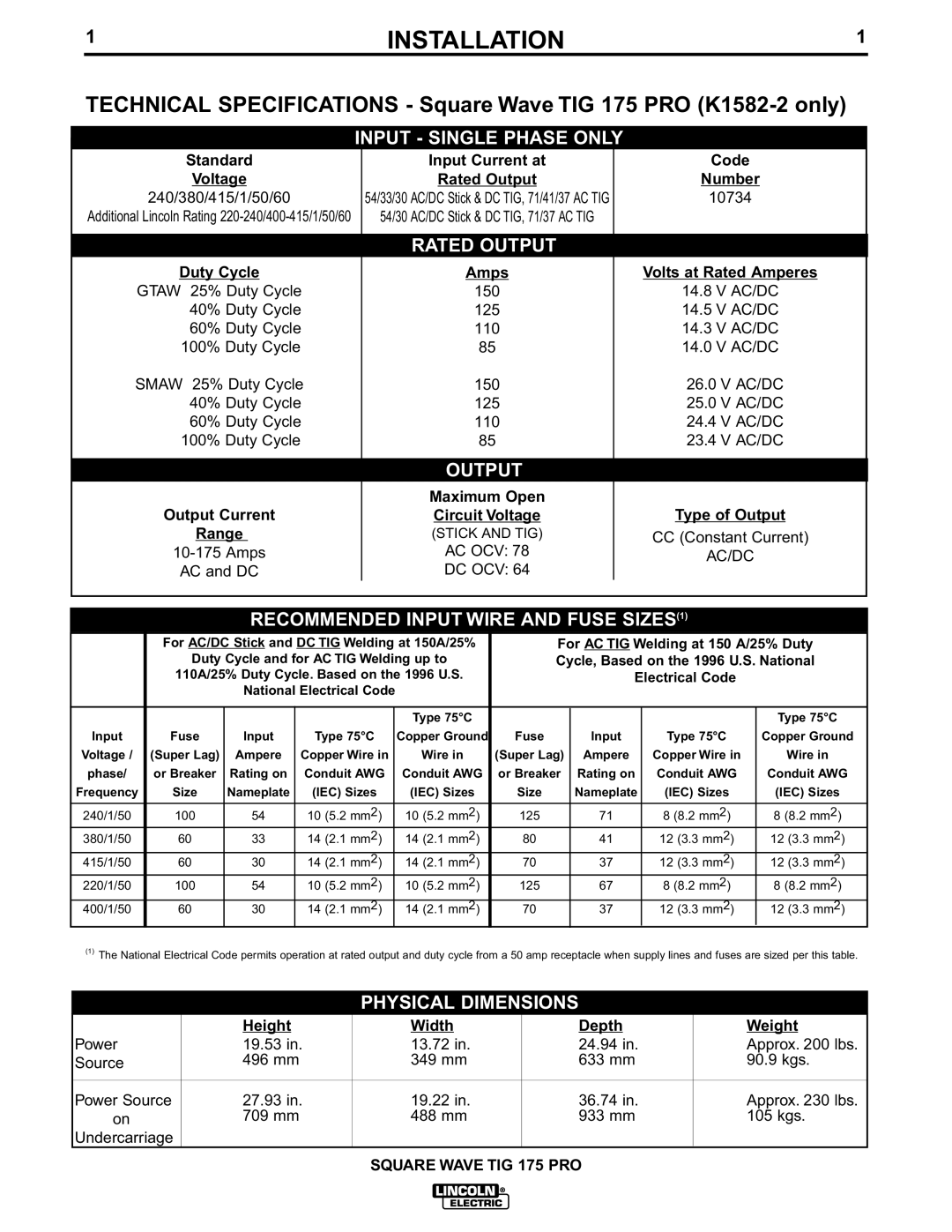
TECHNICAL SPECIFICATIONS - Square Wave TIG 175 PRO
INPUT - SINGLE PHASE ONLY
Standard
Voltage
240/380/415/1/50/60
Additional Lincoln Rating
Duty Cycle
GTAW 25% Duty Cycle
40% Duty Cycle
60% Duty Cycle
100% Duty Cycle
SMAW 25% Duty Cycle
40% Duty Cycle
60% Duty Cycle
100% Duty Cycle
Output Current
Range
AC and DC
Input Current at
Rated Output
54/33/30 AC/DC Stick & DC TIG, 71/41/37 AC TIG
54/30 AC/DC Stick & DC TIG, 71/37 AC TIG
RATED OUTPUT
Amps
150
125
110
85
150
125
110
85
OUTPUT
Maximum Open
Circuit Voltage
(STICK AND TIG)
AC OCV: 78
DC OCV: 64
Code
Number
10734
Volts at Rated Amperes
14.8V AC/DC
14.5V AC/DC
14.3V AC/DC
14.0V AC/DC
26.0V AC/DC
25.0V AC/DC
24.4V AC/DC
23.4V AC/DC
Type of Output
CC(Constant Current) AC/DC
RECOMMENDED INPUT WIRE AND FUSE SIZES(1)
|
|
|
|
|
|
|
|
|
|
|
|
|
|
|
|
|
|
|
|
|
|
|
|
|
|
|
|
| For AC/DC Stick and DC TIG Welding at 150A/25% |
|
| For AC TIG Welding at 150 A/25% Duty |
|
| |||||||||||||
|
|
|
|
| Duty Cycle and for AC TIG Welding up to |
|
| Cycle, Based on the 1996 U.S. National |
|
| |||||||||||||
|
|
|
|
| 110A/25% Duty Cycle. Based on the 1996 U.S. |
|
|
| Electrical Code |
|
|
| |||||||||||
|
|
|
|
|
|
| National Electrical Code |
|
|
|
|
|
|
|
|
|
|
|
| ||||
|
|
|
|
|
|
|
|
|
|
|
|
|
|
|
|
|
|
|
|
|
|
|
|
|
|
|
|
|
|
|
|
|
|
|
| Type 75°C |
|
|
|
|
|
|
| Type 75°C |
| ||
| Input |
|
|
| Fuse |
| Input |
|
| Type 75°C |
| Copper Ground | Fuse | Input |
| Type 75°C |
|
| Copper Ground |
| |||
| Voltage / |
|
| (Super Lag) |
| Ampere |
|
| Copper Wire in |
| Wire in | (Super Lag) | Ampere |
| Copper Wire in |
|
| Wire in |
| ||||
| phase/ |
|
| or Breaker |
| Rating on |
|
| Conduit AWG |
| Conduit AWG | or Breaker | Rating on |
| Conduit AWG |
|
| Conduit AWG |
| ||||
| Frequency |
|
|
| Size |
| Nameplate |
|
| (IEC) Sizes |
| (IEC) Sizes | Size | Nameplate |
| (IEC) Sizes |
|
| (IEC) Sizes |
| |||
| 240/1/50 |
|
| 100 |
| 54 |
|
| 10 (5.2 mm2) |
| 10 (5.2 mm2) | 125 | 71 |
| 8 (8.2 mm2) |
|
| 8 (8.2 mm2) |
| ||||
| 380/1/50 |
|
| 60 |
| 33 |
|
| 14 (2.1 mm2) |
| 14 (2.1 mm2) | 80 |
| 41 |
| 12 (3.3 mm2) |
|
| 12 (3.3 mm2) |
| |||
| 415/1/50 |
|
| 60 |
| 30 |
|
| 14 (2.1 mm2) |
| 14 (2.1 mm2) | 70 |
| 37 |
| 12 (3.3 mm2) |
|
| 12 (3.3 mm2) |
| |||
| 220/1/50 |
|
| 100 |
| 54 |
|
| 10 (5.2 mm2) |
| 10 (5.2 mm2) | 125 | 67 |
| 8 (8.2 mm2) |
|
| 8 (8.2 mm2) |
| ||||
| 400/1/50 |
|
| 60 |
| 30 |
|
| 14 (2.1 mm2) |
| 14 (2.1 mm2) | 70 |
| 37 |
| 12 (3.3 mm2) |
|
| 12 (3.3 mm2) |
| |||
|
|
|
|
|
|
|
|
|
|
|
|
|
|
|
|
|
|
|
|
|
|
|
|
(1)The National Electrical Code permits operation at rated output and duty cycle from a 50 amp receptacle when supply lines and fuses are sized per this table.
PHYSICAL DIMENSIONS
| Height | Width | Depth | Weight |
Power | 19.53 in. | 13.72 in. | 24.94 in. | Approx. 200 lbs. |
Source | 496 mm | 349 mm | 633 mm | 90.9 kgs. |
|
|
|
|
|
Power Source | 27.93 in. | 19.22 in. | 36.74 in. | Approx. 230 lbs. |
on | 709 mm | 488 mm | 933 mm | 105 kgs. |
Undercarriage |
|
|
|
|
