PAGE 10 | BIASI B/40 |
|
|
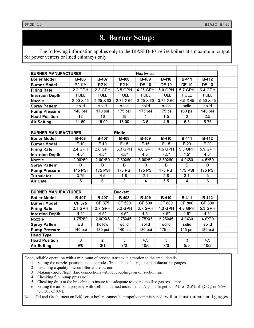
8. Burner Setup:
The following information applies only to the BIASI
BURNER MANUFACTURER |
|
| Heatwise |
|
|
|
| |
Boiler Model |
| |||||||
Burner Model |
| |||||||
Firing Rate | 2.2 GPH | 2.8 GPH | 3.5 GPH | 4.25 GPH | 5.0 GPH | 5.7 GPH | 6.4 GPH |
|
Insertion Depth | FULL | FULL | FULL | FULL | FULL | FULL | FULL |
|
Nozzle | 2.00 X 45 | 2.25 X 60 | 2.75 X 60 | 3.25 X 60 | 3.75 X 60 | 4.5 X 45 | 5.50 X 45 |
|
Spray Pattern | solid | solid | solid | solid | solid | solid | solid |
|
Pump Pressure | 140 psi | 170 psi | 175 psi | 175 psi | 175 psi | 160 psi | 140 psi |
|
Head Position | 12 | 16 | 18 | 1 | 1.5 | 2 | 2.5 |
|
Air Setting | 11.50 | 15.00 | 18.00 | 3.5 | 4.5 | 5.5 | 6.75 |
|
|
|
|
|
|
|
|
|
|
|
|
|
|
|
|
|
|
|
BURNER MANUFACTURER |
| Riello |
|
|
|
|
| |
Boiler Model |
| |||||||
Burner Model |
| |||||||
Firing Rate | 2.4 GPH | 2.6 GPH | 3.3 GPH | 4.0 GPH | 4.6 GPH | 5.3 GPH | 5.9 GPH |
|
Insertion Depth | 4.5" | 4.5" | 4.5" | 4.5" | 4.5" | 4.5" | 4.5" |
|
Nozzle | 2.00X60 | 2.00X60 | 2.50X60 | 3.00X60 | 3.50X60 | 4.0X60 | 4.5X60 |
|
Spray Pattern | B | B | B | B | B | B | B |
|
Pump Pressure | 145 PSI | 175 PSI | 175 PSI | 175 PSI | 175 PSI | 175 PSI | 175 PSI |
|
Turbulator | 3.75 | 4.5 | 1.8 | 2.1 | 2.8 | 3.1 | 5 |
|
Air Gate | 5 | 6 | 3 | 4 | 5.5 | 4 | 6 |
|
|
|
|
|
|
|
|
|
|
BURNER MANUFACTURER |
| Beckett |
|
|
|
|
| |
Boiler Model |
| |||||||
Burner Model | CF 375 | CF 375 | CF 500 | CF 500 | CF 800 | CF 800 | CF 800 |
|
Firing Rate | 2.1 GPH | 2.7 GPH | 3.2 GPH | 3.7 GPH | 4.3 GPH | 4.8 GPH | 5.3 GPH |
|
Insertion Depth | 4.5" | 4.5" | 4.5" | 4.5" | 4.5" | 4.5" | 4.5" |
|
Nozzle | 1.75X60 | 2.00X45 | 2.75X45 | 2.75X45 | 3.25X45 | 4.0X30 | 4.0X30 |
|
Spray Pattern | ES | hollow | solid | solid | solid | solid | solid |
|
Pump Pressure | 140 psi | 180 psi | 140 psi | 180 psi | 175 psi | 145 psi | 180 psi |
|
Head Type |
|
|
|
|
|
|
|
|
Head Position | 0 | 2 | 3 | 4.5 | 3 | 3 | 4.5 |
|
Air Setting | 9/0 | 3/1 | 7/0 | 10/0 | 7/0 | 8/0 | 10/2 |
|
|
|
|
|
|
|
|
|
|
Good, reliable operation with a minimum of service starts with attention to the small details:
1.Setting the nozzle position and electrodes "by the book" using the manufacturer's gauges.
2.Installing a quality micron filter at the burner.
3.Making careful/tight flare connections without couplings on oil suction line.
4.Checking fuel pump pressure.
5.Checking draft at the breeching to insure it is adequate to overcome flue gas resistance.
6.Setting the air band properly with well maintained instruments. A good target is 11% to 12.5% of (CO2) or 6.5% to 3.8% of (O2).
Note: Oil and Gas burners on
