|
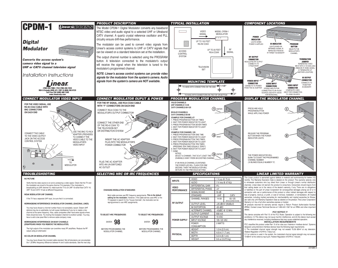
| PRODUCT DESCRIPTION |
| TYPICAL INSTALLATION |
|
|
|
|
| COMPONENT LOCATIONS |
|
| ||||||
| The Model |
|
|
|
|
|
|
|
|
|
|
|
|
| ||||
| NTSC video and audio signal to a selected UHF or Ultraband |
| VIDEO |
|
| MODEL |
|
|
|
|
|
| ||||||
|
| CATV channel. A quartz crystal reference oscillator and PLL |
| SIGNAL |
|
|
| MODULATOR |
|
|
|
|
|
| ||||
|
|
|
|
|
|
|
|
|
| POWER |
|
|
|
| ||||
|
| circuitry ensure |
|
|
|
|
|
|
|
|
|
|
|
|
| |||
Digital |
|
|
| UP TO 150 FEET |
|
|
|
| INDICATOR |
|
|
|
| |||||
| The modulator can be used to | convert video | signals from |
|
|
|
|
| LIGHTS WHEN | IR INDICATOR |
|
|
| |||||
|
|
|
|
|
|
| POWER IS APPLIED |
| PROGRAM |
| ||||||||
Modulator |
| Linear’s access control systems to UHF or CATV signals that |
|
|
|
|
|
|
|
|
| LIGHTS WHEN AN |
| BUTTON |
| |||
|
|
| UP TO 25 FEET | RF |
|
| INFRARED SIGNAL IS |
| SELECTS THE |
| ||||||||
| can be viewed on a standard television set at the installation. | ACCESS |
|
|
| REPEATED FROM AN |
| MODULATOR'S |
| |||||||||
|
|
|
| SIGNAL |
|
| IR TARGET ACCESSORY |
| ||||||||||
|
| CONTROL |
|
|
|
| CHANNEL |
| ||||||||||
|
|
|
|
|
|
|
|
|
|
|
|
|
|
|
|
| ||
|
| The output channel number is selected using the PROGRAM | SYSTEM |
|
|
|
|
|
|
| RF OUTPUT |
|
|
|
| |||
Converts the access system’s |
|
|
|
|
|
|
|
|
|
|
| TERMINATION | ||||||
| button. A television connected | to the modulator’s output |
|
|
|
|
|
|
|
| CONNECTOR |
|
| |||||
camera video signal to a |
|
|
|
|
|
|
|
|
| MODULATED RF OUTPUT |
|
|
| JUMPER | ||||
| will receive the signal when the | television is | tuned to the |
|
|
|
|
|
|
|
| CONNECTS TO |
|
| TERMINATES VIDEO | |||
UHF or CATV channel television signal |
| TELEVISION |
|
|
|
|
| A TELEVISION |
|
| INPUT WITH A 75 OHM LOAD | |||||||
modulator’s programmed channel. |
|
|
|
|
|
|
|
|
|
| ||||||||
|
|
|
|
|
|
|
|
|
|
| (REMOVE IF VIDEO SIGNAL | |||||||
|
|
|
|
| SET |
|
|
|
|
|
|
|
|
| IS TERMINATED AT | |||
|
|
|
|
|
|
|
|
|
|
|
|
|
|
|
| |||
Installation Instructions |
| NOTE: Linear’s access control systems can provide video |
|
|
|
|
|
|
|
|
|
|
| ANOTHER LOCATION) | ||||
|
|
|
|
|
|
|
|
|
|
|
|
|
| |||||
| signals for the modulator from the system’s camera. Audio |
|
|
|
|
|
|
|
|
|
|
|
| IR OUTPUT | ||||
|
|
|
|
|
|
|
|
|
|
|
|
|
| |||||
|
| signals from the system’s camera are NOT available. | MOUNTING TEMPLATE |
|
| POWER INPUT |
|
|
| CONNECTOR | ||||||||
|
|
|
|
|
|
| CONNECTS TO | |||||||||||
|
|
|
| CONNECTOR | AUDIO INPUT |
|
| |||||||||||
|
|
|
|
|
|
|
|
|
|
|
|
| VIDEO INPUT | IR EMITTER | ||||
|
|
|
|
|
|
|
|
|
|
|
| CONNECTS TO POWER | CONNECTORS |
| ||||
|
|
|
|
|
| TO HANG WITH CONNECTORS ON THE SIDE |
|
| ACCESSORY | |||||||||
(760) |
|
|
|
|
|
|
|
| FROM THE AC ADAPTER | STEREO INPUTS FOR |
| CONNECTOR | ||||||
|
|
|
|
|
|
|
|
|
|
|
|
|
|
| ||||
USA & Canada (800) |
|
|
|
|
|
|
|
|
|
|
|
| CONNECTION TO AN AUDIO |
| COMPOSITE VIDEO |
| ||
Toll Free FAX (800) |
|
|
|
|
|
|
|
|
|
|
|
| 2" | SOURCE (USE BOTH JACKS | INPUT FOR CONNECTION | |||
www.linearcorp.com |
|
|
|
|
| TO HANG WITH CONNECTORS ON THE TOP OR BOTTOM |
| FOR MONAURAL) |
| TO VIDEO SOURCE |
| |||||||
|
|
|
|
|
|
|
|
| ||||||||||
CONNECT MODULATOR VIDEO INPUT | CONNECT MODULATOR OUPUT & POWER | PROGRAM MODULATOR CHANNEL |
|
| DISPLAY THE MODULATOR CHANNEL | |||||||||||||
FOR THE VIDEO SIGNAL, USE |
| FOR THE RF SIGNAL, USE |
| VALID CHANNELS: |
|
|
|
|
|
|
|
|
|
|
|
| ||
| WITH "F" CONNECTORS ON EACH END |
|
| UHF CHANNELS |
|
|
|
|
|
|
|
|
|
|
|
| ||
|
|
|
|
|
|
|
|
|
|
|
|
|
|
|
| |||
|
|
|
|
| CATV CHANNELS |
|
|
| 1 | ENTER |
|
| PRESS AND HOLD |
|
| 1 |
| |
BNC CONNECTORS |
| CONNECT |
|
|
|
|
|
|
|
|
|
|
| |||||
|
|
|
|
|
|
|
|
| PROGRAM BUTTON |
|
| |||||||
ON EACH END |
| MODULATOR'S OUTPUT CONNECTOR |
|
| INVALID CHANNELS: |
|
|
|
|
|
|
|
|
|
| |||
|
|
|
|
|
|
|
|
|
| WHILE APPLYING POWER |
|
|
| |||||
|
|
|
|
|
| CATV CHANNELS |
|
|
|
|
|
|
|
|
|
|
|
|
|
|
|
|
|
| EXAMPLE FOR CHANNEL 67: |
|
|
|
|
|
|
|
|
|
|
| |
|
|
|
|
|
| 1. PRESS PROGRAM BUTTON SIX TIMES |
|
|
|
|
|
|
|
|
|
|
| |
|
| CONNECT THE OTHER END |
|
| 2. WAIT FOR POWER INDICATOR TO LIGHT |
|
|
|
|
|
|
|
|
|
|
| ||
|
| OF THE |
|
| 3. PRESS PROGRAM BUTTON SEVEN TIMES |
|
|
|
|
|
|
|
|
|
|
| ||
|
| THE TELEVISION SET |
|
| 4. WAIT FOR POWER INDICATOR TO LIGHT |
|
|
|
|
|
|
|
|
|
|
| ||
|
|
|
| 5. DONE |
|
|
|
|
|
|
|
|
|
|
|
| ||
| USE THE | OR DISTRIBUTION SYSTEM |
|
|
|
|
|
|
|
|
|
|
|
|
|
| ||
CONNECT THE CABLE |
|
| EXAMPLE FOR CHANNEL 120: |
|
|
|
|
|
| RELEASE THE PROGRAM |
|
|
| |||||
|
|
|
|
|
|
|
|
|
|
|
|
| ||||||
ADAPTER (PROVIDED) |
|
|
|
| 1. PRESS PROGRAM BUTTON ONE TIME |
|
| 2 |
|
|
|
| 2 |
| ||||
TO THE VIDEO OUTPUT |
|
|
|
|
|
| WAIT |
|
| BUTTON WHEN THE POWER |
|
| ||||||
TO CONNECT THE |
|
|
|
| 2. WAIT FOR POWER INDICATOR TO LIGHT |
|
|
|
|
|
| |||||||
JACK ON THE ACCESS | INSERT THE AC ADAPTER |
|
|
|
|
|
|
| INDICATOR LIGHTS |
|
|
|
| |||||
VIDEO CABLE TO THE |
|
| 3. PRESS PROGRAM BUTTON TWO TIMES |
|
|
|
|
|
|
|
|
|
| |||||
CONTROL SYSTEM |
|
|
|
|
|
|
|
|
|
|
|
|
| |||||
MODULATOR'S | PLUG INTO THE MODULATOR'S |
|
| 4. WAIT FOR POWER INDICATOR TO LIGHT |
|
|
|
|
|
|
|
|
|
|
| |||
| VIDEO INPUT | POWER CONNECTOR |
|
| 5. PRESS PROGRAM BUTTON TEN TIMES |
|
|
|
|
|
|
|
|
|
|
| ||
|
|
|
|
|
| (PRESSING TEN TIMES EQUALS "ZERO") |
|
|
|
|
|
|
|
|
|
|
| |
|
|
|
|
|
| 6. WAIT FOR POWER INDICATOR TO LIGHT |
|
|
|
|
|
|
|
|
|
|
| |
|
|
|
|
|
| 7. DONE |
|
|
|
|
|
|
|
|
|
|
|
|
|
|
|
|
|
| NOTES: |
|
|
| 3 ENTER |
|
| THE POWER INDICATOR WILL |
|
|
| ||
|
|
|
|
|
| SELECT A CHANNEL THAT IS AT LEAST TWO |
|
|
|
|
| |||||||
|
|
|
|
|
|
|
|
|
| BLINK TO COUNT THE PROGRAMMED |
|
|
| |||||
|
|
|
|
|
| CHANNELS AWAY FROM AN EXISTING CHANNEL |
|
|
|
| 3 |
| ||||||
|
| PLUG THE AC ADAPTER |
|
|
|
|
| CHANNEL NUMBER |
|
|
| |||||||
|
|
|
|
|
|
|
|
|
|
|
|
|
|
|
| |||
TO |
|
|
| IF AN INVALID CHANNEL IS ENTERED, |
|
|
|
|
|
| (10 BLINKS EQUALS NUMBER "0") |
|
|
| ||||
MODULATOR | INTO AN |
|
| THE POWER LED WILL FLASH FOR ONE |
|
|
|
|
|
|
|
|
|
|
| |||
|
| AC OUTLET |
|
|
| SECOND, THEN THE MODULATOR WILL |
|
|
|
|
|
|
|
|
|
|
| |
|
|
|
|
|
| RETURN TO THE PREVIOUS SETTING |
|
|
|
|
|
|
|
|
|
|
| |
TROUBLESHOOTING |
| SELECTING HRC OR IRC FREQUENCIES |
| SPECIFICATIONS |
|
| LINEAR LIMITED WARRANTY | |||||||||||
NO PICTURE |
|
|
|
|
|
| VIDEO |
|
|
| 1 V |
| This Linear product is warranted against defects in material and workmanship for twelve (12) | |||||
|
|
|
|
| INPUTS |
|
|
|
| months. The Warranty Expiration Date is labeled on the product. This warranty extends only | ||||||||
|
|
|
|
|
|
|
|
|
| |||||||||
Verify that the video source is on and is producing a video signal. Check that the TV and |
|
|
|
| AUDIO |
|
|
| 1 V rms @ 47 KΩ |
| to wholesale customers who buy direct from Linear or through Linear’s normal distribution | |||||||
|
|
|
|
|
|
|
|
| ||||||||||
the modulator are tuned to the same channel. For example, if the modulator is |
|
|
|
| VIDEO | DIFFERENTIAL GAIN |
| 4% |
|
| channels. Linear does not warrant this product to consumers. Consumers should inquire from | |||||||
broadcasting on UHF channel 16, make sure the TV is on UHF 16 rather than CATV 16. |
|
|
|
| DIFFERENTIAL PHASE |
| <4° |
|
| their selling dealer as to the nature of the dealer’s warranty, if any. There are no obligations | ||||||||
UHF 16 and CATV 16 are at different frequencies. |
| CHANGING MODULATION STANDARDS |
|
| PERFORMANCE |
|
|
| or liabilities on the part of Linear Corporation for consequential damages arising out of or in | |||||||||
|
|
| SIGNAL/NOISE |
|
|
| 55 dB |
|
| |||||||||
WEAK MODULATOR UHF CHANNEL |
|
|
|
|
|
|
|
|
|
|
| connection with use or performance of this product or other indirect damages with respect to | ||||||
| Most cable services use IRC frequency assignments. This is the default |
| STANDARD |
|
|
| UHF | CATV | loss of property, revenue, or profi t, or cost of removal, installation, or reinstallation. All implied | |||||||||
If the TV has a separate UHF input, be sure that it is connected. | setting for the modulator. However, if the cable service uses HRC or the |
| CHANNEL RANGES |
|
| warranties, including implied warranties for merchantability and implied warranties for fi tness, | ||||||||||||
TV appears to search for the "house channels", the modulator can be |
|
| are valid only until Warranty Expiration Date as labeled on the product. This Linear Corporation | |||||||||||||||
|
|
|
|
|
|
|
| (EXCLUDING | ||||||||||
|
| reprogrammed to use HRC assignments. |
| RF OUTPUT |
|
|
|
|
| Warranty is in lieu of all other warranties express or implied. |
| |||||||
HERRINGBONE INTERFERENCE ON MODULATOR CHANNEL (DIAGONAL LINES) |
| OUTPUT LEVEL |
|
|
| +25 dBmV (90dBuV) |
|
| ||||||||||
|
|
|
|
|
|
|
|
| All products returned for warranty service require a Return Product Authorization Number | |||||||||
You may have chosen a channel number that is not completely vacant. Distant UHF |
|
|
|
|
| IM DISTORTION |
|
|
|
|
|
| (RPA#). Contact Linear Technical Service at | |||||
stations may be |
|
|
|
|
| ALTERNATE CHANNEL |
|
| details. | FCC NOTICE !!! |
| |||||||
channel at the same frequency. Also, cable companies often have extra signals where |
|
|
|
|
| OUTPUT CURRENT |
| 600 mA |
|
|
|
| ||||||
there should be none. Try moving the modulator channel to another number. You may | TO SELECT HRC FREQUENCIES | TO SELECT IRC FREQUENCIES |
|
|
|
| This device complies with Part 15 of the FCC Rules. Operation is subject to the following two | |||||||||||
| OUTPUT VOLTAGE |
|
| 15 VDC |
|
| ||||||||||||
have to add a low pass filter to remove cable company noise. |
|
| 98 |
| 99 |
|
|
|
|
| conditions: (1) This device may not cause harmful interference, and (2) this device must accept | |||||||
HERRINGBONE INTERFERENCE ON MANY CHANNELS |
| ENTER: | ENTER: | POWER SUPPLY INPUT VOLTAGE |
|
|
|
| any interference received, including interference that may cause undesired operation. | |||||||||
|
| POWER |
|
|
| 5 WATTS |
|
|
| INSTALLATION REQUIREMENTS |
| |||||||
(DISAPPEARS WHEN YOU REMOVE THE MODULATOR) |
|
|
|
|
|
|
|
|
| FCC classifi es this product under Part 15 of its rules as a “television interface device”. Systems | ||||||||
The high output of the modulator can overdrive many RF amplifiers. Reduce the RF | BEFORE PROGRAMMING THE | BEFORE PROGRAMMING THE |
| CONSUMPTION |
|
|
|
|
|
| designed using television interface devices have the following legal requirements: | |||||||
| HEIGHT |
|
|
| 1.0 in (2.5 cm) |
| 1) The modulated channel signal strength may not exceed 15.56 dBmV at any television. | |||||||||||
output using an attentuator. |
|
|
|
|
|
| ||||||||||||
| MODULATOR CHANNEL | MODULATOR CHANNEL |
| WIDTH |
|
|
| 4.6 in (11.7 cm) |
| Federal Regulation 47CFR15.115(b)(1)(i). |
|
|
| |||||
|
| PHYSICAL |
|
|
|
|
|
|
| |||||||||
|
|
|
|
|
|
|
|
|
| 2) If an antenna is used in the system, the modulated channel signal strength may not exceed | ||||||||
NO COLOR ON MODULATOR CHANNEL |
|
|
|
|
| DEPTH |
|
|
| 3.2 in (8.1 cm) |
| |||||||
|
|
|
|
|
|
|
|
|
|
| ||||||||
|
|
|
|
|
|
| WEIGHT |
|
|
| 9.6 oz (0.273 kg) |
|
| |||||
You may have chosen the incorrect cable standard. Not all televisions can accomodate |
|
|
|
|
|
|
|
|
|
|
|
|
|
| ||||
|
|
|
|
|
|
|
|
|
|
|
|
|
|
|
|
| ||
the 1.25 MHz frequency difference between H and I cable standards. See the next step. |
|
|
|
|
|
|
|
|
|
|
|
|
|
|
|
|
| |
221695 A