DXT-31
BY
DOOR/WINDOW
TRANSMITTER
Installation Instructions
(619)
USA & Canada (800)
Toll Free FAX (800)
TRANSMITTER
TEST/OPERATE
INDICATOR
NOTCH ON SIDE OF
TRANSMITTER
ALIGN MAGNET
NEXT TO NOTCH
MAGNET | PUSH CASE |
1/2" SPACE | TO TEST |
MAXIMUM |
|
| PRODUCT DESCRIPTION |
The
The digital DX code format features over a million possible codes. The DX transmitters are precoded at the factory to unique codes, so no field coding is required. The
For versatility, any transmitter can be programmed into any receiver channel. Receivers must be programmed to the transmitter code before system testing and operation. Refer to the receiver’s instructions for details on programming.
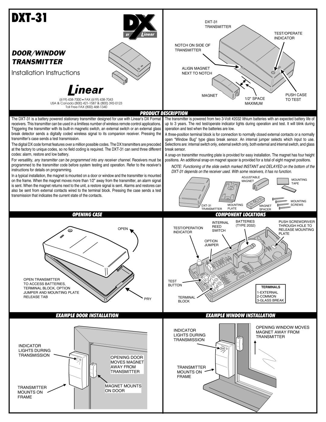
In a typical installation, the magnet is mounted on a door or window and the transmitter is mounted on the frame. When the magnet moves more than 1/2" away from the transmitter, an alarm signal is sent. When the magnet returns next to the unit, a restore signal is sent. Alarms and restores can also be sent from external contacts wired to the terminal block. Pressing the case sends a test transmission that indicates the current state of the contacts.
OPENING CASE
The transmitter is powered from two
A
A
NOTE: Functioning of the slide switch marked INSTANT and DELAYED on the bottom of the
ADJUSTABLE
MAGNETMOUNTING
TAPE
|
|
| MOUNTING |
MOUNTING | MAGNET | SCREWS | |
TRANSMITTER | PLATE | SPACER |
|
COMPONENT LOCATIONS
OPEN
OPEN TRANSMITTER TO ACCESS BATTERIES,
TERMINAL BLOCK, OPTION JUMPER AND MOUNTING PLATE
RELEASE TAB
PRY
| INTERNAL | BATTERIES | |
| (TYPE 2032) | ||
TEST/OPERATION | REED | ||
| |||
SWITCH |
| ||
INDICATOR |
| ||
|
| ||
| OPTION |
| |
| JUMPER |
|
TEST | 1 | |
2 | ||
BUTTON | ||
3 | ||
|
TERMINAL
BLOCK
PUSH SCREWDRIVER
THROUGH HOLE TO
RELEASE MOUNTING
PLATE
TERMINALS
EXAMPLE DOOR INSTALLATION
EXAMPLE WINDOW INSTALLATION
INDICATOR LIGHTS DURING TRANSMISSION
OPENING WINDOW MOVES MAGNET AWAY FROM TRANSMITTER
INDICATOR LIGHTS DURING TRANSMISSION
TRANSMITTER MOUNTS ON FRAME
OPENING DOOR MOVES MAGNET AWAY FROM TRANSMITTER
MAGNET MOUNTS ON DOOR
TRANSMITTER MOUNTS ON ![]() FRAME
FRAME