4 Testing the Infrared Safety Beam
The safety beam has two components, a sender and a receiver. The sender produces a narrow infrared beam that travels across the bottom of the door opening to the infrared receiver. If an object blocks the infrared beam while the door is closing, the door will stop, then reverse and fully open (the opener’s light will fl ash three times).
As a safety feature, the opener will ignore signals from all remote controls if the door is open and the
6 Testing & Adjusting the Door Force Safety System
The door force adjustments are located on the side of the opener. The door force adjustments must be properly set at all times. The CLOSE FORCE adjustment controls how much force is required to cause the door to reverse direction if an obstruction is encountered during closing. The OPEN FORCE adjustment controls how much force is required to stop the door if an obstruction is encountered during opening.
infrared safety beam is blocked or out of alignment. In this case, the door can be forced closed by pressing and holding the wall station’s up/down arrow pushbutton (be sure the door area is in clear view).
WARNING
SETTING THE DOOR FORCE |
WARNING
With the door closed, disengage the trolley from the chain during these alignment tests by pulling the red release handle.
Safety Beam Test
1 | Check that the opener has power. The green lights on |
| the sender and receiver should be lit. |
2 | If the receiver’s green light is on, but the red light is off, |
| the receiver has power but is not detecting the infrared |
WARNING
Serious injury or death from a closing garage door may result because of failure to test and adjust safety reverse system. Repeat this test monthly and adjust as needed.
SAFETY BEAM INDICATORS
Too much door force will interfere with the proper operation of the safety system. SOMEONE COULD BE SERIOUSLY INJURED OR KILLED IF THE DOOR FORCE IS SET TOO HIGH. A closing door might not reverse properly when required and someone could be pinned under it. An opening door might not stop when going up and someone hanging on the door could get pinned between the door and the header. Do not increase the door force beyond what is required to move the
ADJUSTING THE OPEN FORCE |
ADJUSTING THE CLOSE FORCE |
DECREASE CLOSE FORCE
beam from the sender. The red light might fl ash when |
the beam is partially detected. This can be caused by |
the safety beam sender and receiver while watching the |
GREEN LIGHT
ON = POWER ON OFF = POWER OFF
RED LIGHT
RED LIGHT
door. DO NOT USE THE DOOR FORCE ADJUSTMENT TO COMPENSATE FOR A BINDING OR STICKING GARAGE DOOR. PERFORM THE SAFETY REVERSAL SYSTEM TEST (STEPS
ADJUSTMENT UNTIL THE DOOR REVERSES MIDWAY WHILE GOING DOWN
receiver’s red light (stay out of the beam while aligning |
it). When the red light stays on, the beam is aligned. |
SAFETY BEAM INDICATOR TABLE
GREEN ON | POWER ON |
|
|
GREEN OFF | POWER OFF |
|
|
RED ON | BEAM OK - NO BLOCKAGE |
|
|
RED OFF | BEAM BLOCKED OR |
|
|
RED FLASHING | BEAM ALIGNED POORLY |
|
|
➤NOTE: If the receiver’s red light remains off, check
for: 1) Dirt on the receiver’s lens, 2) Sunlight shining into the receiver’s lens, 3) A short in the safety beam wiring (from staples or at the opener terminals).
3With the door closed and the opener disengaged from the door, press the wall station’s UP/DOWN ARROW button to move the traveler (the part on the belt or chain that the trolley engages with) to the up position (away from the door).
4Push the wall station’s UP/DOWN ARROW button again. While the traveler is moving to the down position (toward the door), block the safety beam. THE TRAVELER
MUST STOP,THEN REVERSE TO THE UP POSITION. The opener’s light should fl ash three times.
5Place an object in the path of the safety beam. Check that constant pressure is required on the wall station’s UP/DOWN ARROW button to cause the traveler to move toward the down position. Release the pushbutton before the opener stops; check that the traveler returns to the up position.
➤NOTE: The garage door opener will not respond to a CLOSE command from a radio transmitter if the safety beam is blocked.
6To reconnect the opener, fl ip the release lever up. Raise the door manually until the opener reconnects.
ON = BEAM ALIGNED, NO OBSTRUCTION
OFF = BEAM NOT ALIGNED, OR OBSTRUCTION
BLINKING = BEAM NEEDS BETTER ALIGNMENT
GREEN LIGHT
ADJUSTING THE BEAM
ADJUST THE SENDER
AND RECEIVER UNTIL
THE RED INDICATOR
LIGHTS SOLID
CHECKING FOR REVERSAL |
|
| |
| THE TRAVELER MUST REVERSE | ||
| WHEN THE BEAM IS INTERRUPTED | ||
|
| DOWN | |
BLOCK THE BEAM |
| UP | |
|
| ||
WHILE THE TRAVELER |
|
| |
IS MOVING DOWN |
| TOWARD | |
TOWARD | OPENER | ||
TRAVELER | |||
DOOR |
| ||
CHECKING FORCED CLOSURE FEATURE | VERIFY THAT CONSTANT | ||
|
| ||
|
| PRESSURE IS REQUIRED | |
|
| ON THE WALL STATION'S | |
|
| PUSHBUTTON TO MAKE | |
|
| THE TRAVELER GO DOWN |
PLACE AN OBJECT
IN THE BEAM'S PATH RELEASE PUSHBUTTON
BEFORE THE OPENER STOPS, THE TRAVELER SHOULD RETURN TO THE UP POSITION
➤NOTE: Read the following directions carefully before changing the door force adjustments.
WARNING
Always perform the Door Force Safety System Test after making any adjustments to the opener.
Door Force Safety System Test
1Start with the door open. Use the remote control to cycle the door during this test.
Adjusting the Close Force
2Turn the CLOSE FORCE adjustment
3Turn the CLOSE FORCE adjustment
Safety Reversal System Test
4Lay a 2 x 4 board fl at on the fl oor where it will be struck by the center of the door as it closes.
5Verify that the door reverses when it strikes the board. The door must reverse within two seconds after striking the board.
➤NOTE: If the door stops after encountering the board and does not reverse, the CLOSE FORCE needs to be
DECREASED.
6 | Repeat the Safety Reversal System Test until the door |
| reverses within two seconds of striking the board. |
7 | Adjusting the Open Force |
Turn the OPEN FORCE adjustment | |
| in the DECREASE direction (counterclockwise) until |
| the door stops mid travel while going up. |
8 | Turn the OPEN FORCE adjustment |
| in the INCREASE direction (clockwise) until the door |
DECREASE
CLOSE FORCE
SETTING THE CLOSE FORCE
INCREASE CLOSE FORCE
ADJUSTMENT UNTIL THE
DOOR CLOSES FULLY
WITHOUT REVERSING
INCREASE
CLOSE FORCE
TESTING THE SAFETY REVERSAL SYSTEM
TEST WITH SMALL OBSTACLE
THE DOOR MUST REVERSE
WITHIN
IMPACT WITH A 2 x 4 BOARD
2 x 4 BOARD LAID FLAT
UNDER CENTER OF DOOR
SETTING THE OPEN FORCE |
DECREASE | INCREASE |
OPEN FORCE | OPEN FORCE |
DECREASE OPEN FORCE | INCREASE OPEN FORCE |
ADJUSTMENT UNTIL THE | ADJUSTMENT UNTIL THE |
DOOR STOPS MIDWAY | DOOR OPENS FULLY |
5 Adjusting the Open and Close Limits
fully opens without stopping. |
WHILE GOING UP | WITHOUT STOPPING |
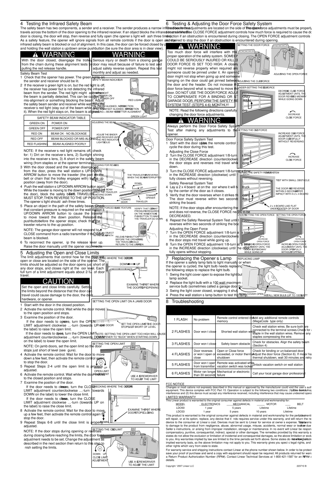
The limit adjustments that control how far the door will open or close are located on the side of the opener. The limits should be adjusted so the door opens just short of any door stops, and closes right at the fl oor level. Each
full turn of a limit adjustment equals about
CAUTION
Set the open and close limits carefully. Setting the limits beyond the distance that the door can travel could cause damage to the door, the door hardware, or opener.
1Start with the door in the closed position.
2Activate the remote control. Wait while the door moves to the open position and stops.
3Examine the position of the door.
•If the door needs to open more, turn the OPEN LIMIT adjustment clockwise
•If the door needs to open less, turn the OPEN LIMIT adjustment counterclockwise
➤NOTE: On jamb doors, set the open limit so the door stops just short of level (see figure).
4Activate the remote control. Wait for the door to move down a few feet, then activate the remote control again to stop the door.
5Repeat Steps
6Activate the remote control. Wait while the door moves to the closed position and stops.
7Examine the position of the door.
•If the door needs to close more, turn the CLOSE LIMIT adjustment counterclockwise
•If the door needs to close less, turn the CLOSE LIMIT adjustment clockwise
8Activate the remote control. Wait for the door to move up a few feet, then activate the remote control again to stop the door.
9Repeat Steps
➤NOTE: If the door stops during opening or reverses during closing before reaching the limits, the door force adjustment needs to be set. Change the adjustment as described in the next section then return to this step to finish setting the limits.
CHECKING WHERE THE DOOR STOPS
DOWN | UP |
EXAMINE THE SPOT WHERE | |
THE DOOR STOPS OPENING |
SETTING THE OPEN LIMIT ON A JAMB DOOR
JAMB DOOR | SET THE OPEN LIMIT SO THE DOOR | |
STOPS JUST SHORT OF LEVEL | ||
|
NOTE: SETTING THE OPEN LIMIT TOO HIGH WILL CAUSE THE OPENER TO "BUCK" WHEN STARTING DOWN
SETTING THE OPEN LIMIT | |
DOWN | UP |
OPEN LIMIT | |
ADJUSTMENT | |
| USE A SCREWDRIVER |
| TO ADJUST THE LIMIT |
CHECKING WHERE THE DOOR STOPS
UP | EXAMINE THE SPOT WHERE |
DOOR STOPS CLOSING |
| DOWN |
|
SETTING THE CLOSE LIMIT |
| |
DOWN | UP |
|
CLOSE LIMIT |
| |
ADJUSTMENT | USE A SCREWDRIVER | |
|
| |
|
| TO ADJUST THE LIMIT |
7 | Replacing the Opener’s Lamp | REPLACING LAMP |
|
If the opener’s safety lamp fails to light manually or when |
|
| |
the opener is cycled, the light bulb needs replacing. Use |
|
| |
the following steps to replace the light bulb. |
|
| |
1 | Swing the light cover open to expose the light bulb and |
|
|
| lamp socket. |
|
|
2 | Replace the light bulb with a 100 watt maximum rough |
|
|
| service bulb (sometimes called a garage door bulb). |
|
|
3 | Swing the light cover closed, snapping it shut. |
|
|
4 | Press the wall station’s lamp button to test the lamp. | SWING COVER OPEN | INSTALL NEW BULB (UP TO 100 WATTS) |
|
8 Troubleshooting
LAMP FLASHES | PROBLEM | CAUSE | REMEDY | |
TROUBLE CODE | ||||
|
|
| ||
|
|
|
| |
1 FLASH | No problem | Remote control entered into | Add any additional remote controls | |
memory | (MegaCode™ type only) | |||
|
| |||
|
|
|
| |
|
|
| Check wall station wires. Be sure both are | |
2 FLASHES | Door won’t close | Shorted wall station wires | connected to the terminal screws.Check for a | |
staple in the wall station wires. Remove any | ||||
|
|
| ||
|
|
| staples compressing the wire. | |
|
|
|
| |
3 FLASHES | Door won’t close | Safety beam obstacle | Check for obstacles. Align the safety beam | |
(Section 4) | ||||
|
|
| ||
|
|
|
| |
4 FLASHES | Door reverses | Open or Close force | Check for binding or | |
or won’t open or | exceeded, or motor thermal | Adjust the door force (Section 6). If motor had | ||
| close | shutdown | thermal shutdown, wait 30 minutes and retry. | |
|
|
|
| |
5 FLASHES | Door won’t open | Remote was activated while | Unlock vacation switch on wall station | |
from transmitter | vacation switch was locked | |||
|
| |||
|
|
|
| |
6 FLASHES | Motor ran longer | Mechanical or electronic | Call your local garage door professional | |
than 30 seconds | failure | |||
|
| |||
|
|
|
|
FCC NOTICE
Changes or modifi cations not expressly described in this manual or approved by the manufacturer could void the user’s authority to operate the equipment. This device complies with FCC Part 15. Operation is subject to the following two conditions: (1) This device may not cause harmful interference and (2) this device must accept any interference received, including interference that may cause undesired operation.
LIMITED WARRANTY
This Linear product is warranted to the original consumer against defects in material and workmanship for:
MODEL | ELECTRONICS | MECHANICAL | MOTOR | BELT |
LDO50 | 1 year | 5 years | Lifetime | Lifetime |
LDO33 | 1 year | 5 years | 10 years | Lifetime |
This product is warranted to the original consumer against defects in material and workmanship for the periods mentioned above. Linear will repair, or at its option, replace, any device that it fi nds requires service under this warranty, and will return the repaired or replaced device to the consumer at Linear’s cost. Devices must be sent to Linear for service at owner’s expense. This warranty does not apply to damage to the product from negligence, abuse, abnormal usage, misuse, accidents, normal wear or tear or due to failure to follow Seller’s instructions, or arising from improper installation, storage or maintenance. In no event will Linear be responsible for incidental, compensatory, punitive, consequential, indirect, special or other damages. The remedies provided by this warranty are exclusive. Some states do not allow the exclusion or limitation of incidental and consequential damages, so the above limitation or exclusion may not apply to you. Any warranties implied by law are limited to the time periods set forth above. Some states do not allow limitations on how long an implied warranty lasts, so the above limitation may not apply to you. This warranty gives you specifi c legal rights, and you may also have other rights which vary from state to state.
For warranty service and shipping instructions contact Linear at the phone number shown below. In order to be protected by this warranty, save your proof of purchase and send a copy with equipment should repair be required. All products returned for warranty service require a Return Product Authorization Number (RPA#). Contact Linear Technical Services at
Copyright © 2007 Linear LLC | 223710 B |