Linksys SD205 Getting to Know the 10/100 Switch, Planning Your Network Layout Overview, power

Models: SD205

1 9
Download 9 pages 13.38 Kb
Page 4
Image 4
Chapter 2: Getting to Know the 10/100 Switch

Chapter 2: Getting to Know the 10/100 Switch

Planning Your Network Layout

Overview

The 5-, 8-, and 16-Port 10/100 Switches differ in number of LEDs and ports. Pictured here is the 5-Port 10/100 Switch; however, the other Switches are sim- ilar in form.

Front Panel LEDs

Figure 2-1

System Green. The System LED will light up when the Switch is powered on.

1-5, 1-8, or 1-16Green. Each LED will light up when there is a connection made through its corresponding port. It will flash when there is activity on its corresponding port.

Back and Side Panel Features

Figure 2-2

The network ports are located on the back panel of the Switch.

1-5, 1-8, or 1-16These ports are connection points for PCs and other network devices, such as additional switches.

Figure 2-3

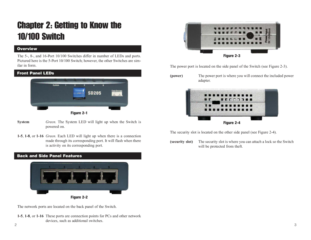
The power port is located on the side panel of the Switch (see Figure 2-3).

(power)

The power port is where you will connect the included power


adapter.

Figure 2-4

The security slot is located on the other side panel (see Figure 2-4).

(security slot) The security slot is where you can attach a lock so the Switch will be protected from theft.

2

3

Page 4
Image 4
Linksys SD205 manual Getting to Know the 10/100 Switch, Planning Your Network Layout Overview, Front Panel LEDs, power