Installation & Operation Manual


6 Gas connections (continued)


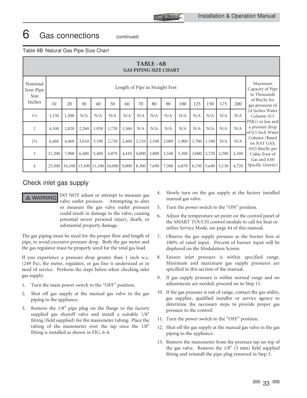
Table 6B Natural Gas Pipe Size Chart


TABLE - 6B


GAS PIPING SIZE CHART


Nominal


Length of Pipe in Straight Feet


Maximum

Iron Pipe


Capacity of Pipe


Size


in Thousands


of Btu/hr for

Inches

10

20

30

40

50

60

70

80

90


100

125

150

175

200


gas pressures of


14 Inches Water

2,150

1,500

N/A

N/A

N/A

N/A

N/A

N/A

N/A


N/A

N/A

N/A

N/A

N/A


Column (0.5


PSIG) or less and


2

4,100

2,820

2,260

1,950

1,720

1,560

N/A

N/A

N/A


N/A

N/A

N/A

N/A

N/A

a pressure drop


of 0.5 Inch Water


6,460

4,460

3,610

3,100

2,720

2,460

2,310

2,100

2,000


1,900

1,700

1,540

N/A

N/A

Column (Based


on NAT GAS,


1025 Btu/hr per

3

11,200

7,900

6,400

5,400

4,870

4,410

4,000

3,800

3,540


3,300

3,000

2,720

2,500

2,340


Cubic Foot of


Gas and 0.60


4

23,500

16,100

13,100

11,100

10,000

9,000

8,300

7,690

7,380


6,870

6,150

5,640

5,130

4,720

Specific Gravity)


Check inlet gas supply

￿WARNING DO NOT adjust or attempt to measure gas valve outlet pressure. Attempting to alter

or measure the gas valve outlet pressure could result in damage to the valve, causing potential severe personal injury, death, or substantial property damage.

The gas piping must be sized for the proper flow and length of pipe, to avoid excessive pressure drop. Both the gas meter and the gas regulator must be properly sized for the total gas load.

If you experience a pressure drop greater than 1 inch w.c. (249 Pa), the meter, regulator, or gas line is undersized or in need of service. Perform the steps below when checking inlet gas supply:

1.Turn the main power switch to the “OFF” position.

2.Shut off gas supply at the manual gas valve in the gas piping to the appliance.

3.Remove the 1/8" pipe plug on the flange to the factory supplied gas shutoff valve and install a suitable 1/8" fitting (field supplied) for the manometer tubing. Place the tubing of the manometer over the tap once the 1/8" fitting is installed as shown in FIG. 6-4.

4.Slowly turn on the gas supply at the factory installed manual gas valve.

5.Turn the power switch to the “ON” position.

6.Adjust the temperature set point on the control panel of the SMART TOUCH control module to call for heat or utilize Service Mode, see page 44 of this manual.

7.Observe the gas supply pressure as the burner fires at 100% of rated input. Percent of burner input will be displayed on the Modulation Screen.

8.Ensure inlet pressure is within specified range. Minimum and maximum gas supply pressures are specified in this section of the manual.

9.If gas supply pressure is within normal range and no adjustments are needed, proceed on to Step 11.

10.If the gas pressure is out of range, contact the gas utility, gas supplier, qualified installer or service agency to determine the necessary steps to provide proper gas pressure to the control.

11.Turn the power switch to the “OFF” position.

12.Shut off the gas supply at the manual gas valve in the gas piping to the appliance.

13.Remove the manometer from the pressure tap on top of the gas valve. Remove the 1/8" (3 mm) field supplied fitting and reinstall the pipe plug removed in Step 3.

33

Page 33
Image 33
Lochinvar 3.5, 2.5 service manual Check inlet gas supply, GAS Piping Size Chart

3, 2, 3.5, 2.5 specifications

The Lochinvar 2, 3, 3.5, and 2.5 models are a standout lineup in the realm of commercial and residential water heating solutions. Known for their advanced technology and high efficiency, these units cater to a wide range of applications, ensuring optimal performance and reliability.

One of the key features of the Lochinvar models is their robust construction. Each unit is designed to withstand rigorous operational demands while providing excellent thermal efficiency. They are equipped with stainless steel heat exchangers, which offer superior resistance to corrosion and extend the lifespan of the equipment. This durability is essential for both commercial and residential settings where demand can vary significantly.

The Lochinvar 2, 3, 3.5, and 2.5 models utilize innovative control systems that enhance their operational efficiency and user convenience. The built-in Smart Control technology allows for easy monitoring and adjusting of system parameters, ensuring that users can maintain optimal performance with minimal effort. This feature is especially beneficial in commercial settings where large volumes of hot water are required, as it enables users to effectively manage their energy consumption.

Energy efficiency is another hallmark of the Lochinvar lineup. With high-efficiency ratings, these models help reduce energy costs significantly, making them an environmentally friendly option for heating water. The use of advanced combustion technology ensures that these units can deliver maximum heat output with minimal fuel consumption.

Additionally, the Lochinvar models are designed with safety and reliability in mind. They feature multiple safety controls and diagnostics that alert users to potential issues before they escalate, providing peace of mind. The integration of advanced venting options allows for flexible installation configurations, accommodating various building layouts and space requirements.

In summary, the Lochinvar 2, 3, 3.5, and 2.5 models define modern water heating technology with their combination of durability, efficiency, and advanced features. With their innovative design and user-friendly controls, they meet the demanding needs of both commercial and residential users, making them a top choice in the water heater market. Whether for new installations or replacements, these units deliver reliable performance and value.