RPV-I&S
FOR YOUR SAFETY READ BEFORE LIGHTING
WARNING: If you do not follow these instructions exactly, a fire or explosion may result causing property damage, personal injury or loss of life.
A.This appliance is equipped with an ignition device which automatically lights the pilot. Do not try to light the pilot by hand.
B.BEFORE OPERATING smell all around the appliance area for gas. Be sure to smell next to the floor because some gas is heavier than air and will settle on the floor.
WHAT TO DO IF YOU SMELL GAS
•Do not try to light any appliance.
•Do not touch any electric switch; do not use any telephone in your building.
•Immediately call your gas supplier from a neighbor’s phone. Follow the gas supplier’s instructions.
•If you cannot reach your gas supplier, call the fire department.
C.Use only your hand to push in or turn the gas control knob. Never use tools. If the knob will not push in or turn by hand, don’t try to repair it, call a qualified service technician. Force or attempted repair may result in a fire or explosion.
D.Do not use this appliance if any part has been under water, immediately call a qualified service technician to inspect the appliance and to replace any part of the control system and any gas control which has been under water.
OPERATING INSTRUCTIONS
1. Stop! Read the safety information above on this label.
2. Turn off all electric power to appliance.
3. Set the thermostat to the lowest setting.
4. This appliance is equipped with on ignition device which automatically lights the pilot. Do not try to light the pilot by hand.
5. Slide the switch on the left side of the gas valve to the “OFF” position.
6. Wait five (5) minutes to clear out any gas. Then smell for gas, including near the floor. If you smell gas, STOP! Follow “B” in the safety information above on this table. If you don’t smell gas, go to the next step.
7. Slide the switch on the left side of the gas valve to the “ON” position.
8. Set thermostat to desired setting.
9. Turn on all electric power to the appliance.
10. If the appliance will not operate, follow the instructiolns “To Turn Off Gas To Appliance” and call your service technician or gas supplier.
TO TURN OFF GAS TO APPLIANCE
1. Turn off all electric power to the appliance.
2. Set the thermostat to lowest setting.
3. Slide the switch on the left side of the gas valve to the “OFF” position.
THERMOSTAT ADJUSTMENT
 CAUTION
Before adjusting thermostat(s), turn off power supply to the water heater.
The thermostat dial is adjusted to approximately 120°F when shipped from the factory. When adjusting the thermostat, it should be remembered that lower temperature settings are more energy efficient. The thermostat cover, on the right side of the gas valve, must be removed when the thermostat is adjusted. To adjust the thermostat turn the dial colckwise with a screwdriver until the minimum acceptable temperture is set. It is suggested that the starting point setting not exceed the 120°F (49°C) or “HOT” setting on the thermostat.
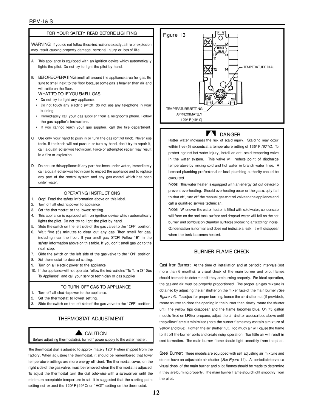
Figure 13

 TEMPERATURE DIAL
TEMPERATURE SETTING |
APPROXIMATELY |
120°F (49°C) |
DANGER
Hotter water increases the risk of scald injury. Scalding may occur within five (5) seconds at a temperature setting of 135°F (57°C). To protect against hot water injury, install an anti-scald tempering valve in the water system. This valve will reduce point of discharge temperature by mixing cold and hot water in branch water lines. A licensed plumbing professional or local plumbing authority should be consulted.
Note: This water heater is equipped with an energy cut out device to prevent overheating. Should overheating occur or the gas supply fail to shut off, turn off the manual gas control valve to the appliance and call a qualified service technician.
Note: Whenever the water heater is filled with cold water, condensate will form on the cool tank surface and drops of water will fall on the hot burner and combustion chamber surfaces producing a “sizzling” noise. Condensation is normal and does not indicate a leak. It will disappear when the tank becomes heated.
BURNER FLAME CHECK
Cast Iron Burner: At the time of installation and at periodic intervals (not more than 6 months), a visual check of the main burner and pilot flames should be made to determine if they are burning properly. For ideal operation, the gas and air must be properly proportioned. The proper air-gas mixture is obtained by adjusting the air shutter on the mixer face of the main burner (See Figure 14). To adjust for proper burning, loosen the air shutter nut (if provided), rotate shutter to close the opening in the burner then slowly rotate the shutter until the yellow tips disappear and the flame becomes blue. On 75 gallon models fired on LPG or propane, adjust the air shutter as described above until the yellow flame is minimized (note-the burner flame may contain a mixture of yellow and blue). Tighten the air shutter nut. Too much air will cause the flame to lift off the burner ports and create noisy operation. Too little air will result in soot formation. The main burner flame should light smoothly from the pilot.
Steel Burner: These models are equipped with self adjusting air mixture and do not have an adjustable air shutter (See Figure 14). At periodic intervals a visual check of the main burner and pilot flames should be made to determine if they are burning properly. The main burner flame should light smoothly from the pilot.