1. Package Contents
4 x Cameras
4x Camera Stands
4 x 100’ (30m) DIN
Extension Cables
Features:
•High Resolution Image Sensor
•24 High Intensity IR LEDs provides effective night vision range up to 50 ft. (15 m)**
•Day / Night mode: Picture automatically switches to B&W delivering better clarity in low light conditions
•Built in microphone provides
•Weatherproof*** Cameras ideal for indoor and outdoor applications (IP66)
•100 ft.(30m) extension cable included per camera
•Ceiling or Wall Mountable Camera with versatile stand provides flexible mounting options
NOTE - This Camera includes a Mechanical Auto IR Cut Filter. When the Camera changes between Day/Night lighting, an audible clicking noise may be heard from the camera. This clicking is nor- mal, and indicates the Camera filter is working.
**Night Vision Range up to 50ft. (15m) in ideal conditions. Objects at or beyond this range may be partially or completely obscured, depending on the camera application.
***Not recommended for submersion in water.
2. Installing the Camera
Note: Test the cameras prior to selecting a permanent mounting location by temporarily connecting the Cameras and Cables to the System.
1.Mount the camera stand to the desired mounting surface. Attach the camera to the supplied stand.
NOTE: The camera can be mounted to either a wall or a ceiling.
2.Aim the camera. Remove the protective film from the lens.
Lift the plastic tab on the lower edge of the camera to remove the protective film.
3.Connect the Extension cable to the camera. Connect the other end of the Extension Cable to the Observation System or DVR.
Note: Confirm that the arrows on the DIN Extension cable are aligned with the Camera Cable and System ports when connecting the cable. If the pins in the DIN Cable are bent, the Camera will NOT function
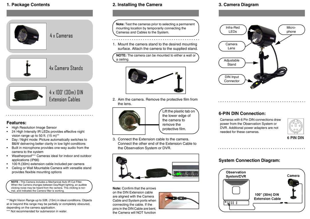
3. Camera Diagram
Micro- | |
LEDs | phone |
Camera
Lens
Adjustable
Stand
DIN Input
Connector
6-PIN DIN Connection:
Cameras with 6 Pin DIN connections draw power from the Observation System or DVR. Additional power adapters are not needed for these cameras.