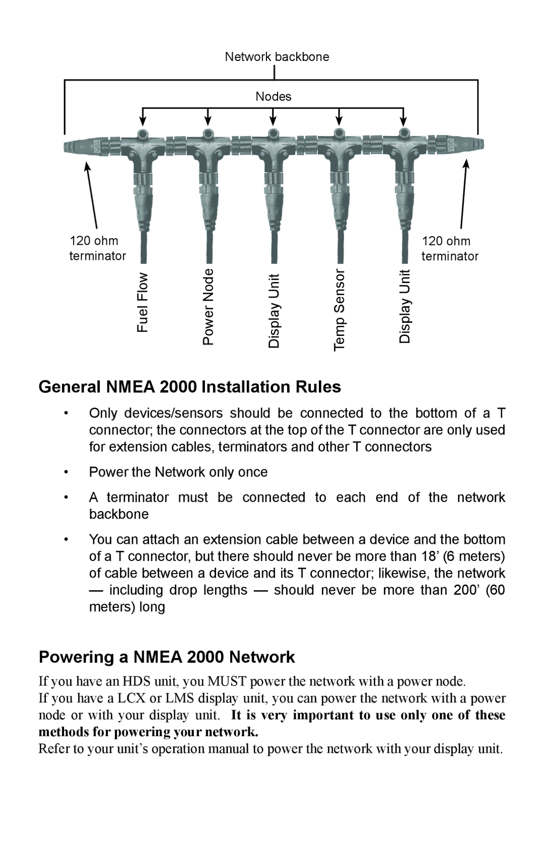
Network backbone
Nodes
120 ohm |
|
|
| 120 ohm |
terminator | Power Node |
|
| terminator |
Fuel Flow | Display Unit | Temp Sensor | Display Unit |
General NMEA 2000 Installation Rules
•Only devices/sensors should be connected to the bottom of a T connector; the connectors at the top of the T connector are only used for extension cables, terminators and other T connectors
•Power the Network only once
•A terminator must be connected to each end of the network backbone
•You can attach an extension cable between a device and the bottom of a T connector, but there should never be more than 18’ (6 meters) of cable between a device and its T connector; likewise, the network
— including drop lengths — should never be more than 200’ (60 meters) long
Powering a NMEA 2000 Network
If you have an HDS unit, you MUST power the network with a power node.
If you have a LCX or LMS display unit, you can power the network with a power node or with your display unit. It is very important to use only one of these methods for powering your network.
Refer to your unit’s operation manual to power the network with your display unit.