Front and Back Panel Descriptions
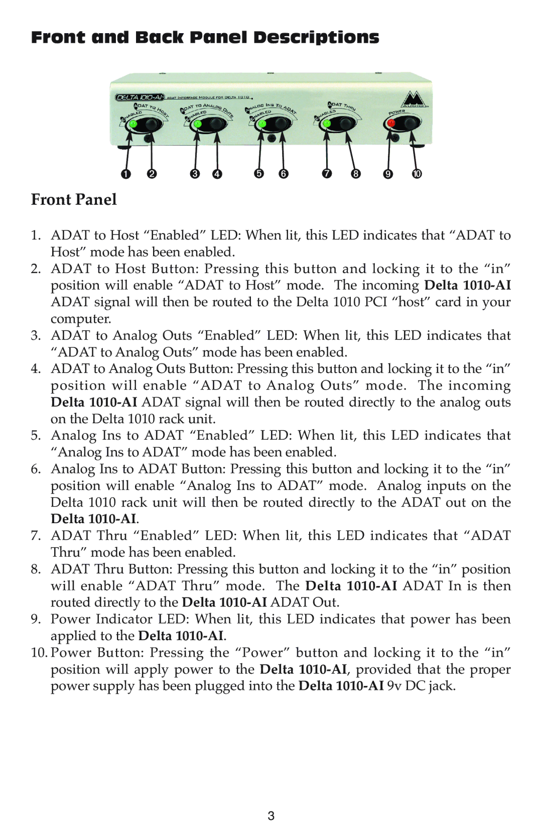
➊ ➋ ➌ ➍ ➎ ➏ | ➐ ➑ ➒ ➓ |
Front Panel
1.ADAT to Host “Enabled” LED: When lit, this LED indicates that “ADAT to Host” mode has been enabled.
2.ADAT to Host Button: Pressing this button and locking it to the “in” position will enable “ADAT to Host” mode. The incoming Delta
3.ADAT to Analog Outs “Enabled” LED: When lit, this LED indicates that “ADAT to Analog Outs” mode has been enabled.
4.ADAT to Analog Outs Button: Pressing this button and locking it to the “in” position will enable “ADAT to Analog Outs” mode. The incoming Delta
5.Analog Ins to ADAT “Enabled” LED: When lit, this LED indicates that “Analog Ins to ADAT” mode has been enabled.
6.Analog Ins to ADAT Button: Pressing this button and locking it to the “in” position will enable “Analog Ins to ADAT” mode. Analog inputs on the Delta 1010 rack unit will then be routed directly to the ADAT out on the Delta
7.ADAT Thru “Enabled” LED: When lit, this LED indicates that “ADAT Thru” mode has been enabled.
8.ADAT Thru Button: Pressing this button and locking it to the “in” position will enable “ADAT Thru” mode. The Delta
9.Power Indicator LED: When lit, this LED indicates that power has been applied to the Delta
10.Power Button: Pressing the “Power” button and locking it to the “in” position will apply power to the Delta
3