DiskOnChip 9x12
2 Using the DiskOnChip 9x12 BGA-to-32-Pin DIP Adapter
2.1Jumper Settings
The adapter contains the following four jumpers:
•J1: Not used, and should be left open.
•J2: Used for the device LOCK# pin. The default setting is open and leaves the LOCK# pin negated.
•JP1 and JP2: Used for matching the host voltage supplied by the EVB or the GANG Programmer, either 3.3V or 5V. Also used for setting the VCCQ for DiskOnChip. See Table 1 for the correct settings.
Table 1: Jumper Settings for Voltage Configuration
Host Voltage | Required VCCQ Voltage | JP1 | JP2 |
5V | 3.3V | ||
5V | 1.8V | ||
3.3V | 3.3V | ||
3.3V | 1.8V |
Note: For devices where VCCQ=VCC, a VCCQ voltage setting of 1.8V will not work.
2.2Inserting the Adapter into a DIP Socket
To insert the adapter into a DiskOnChip EVB or GANG Programmer equipped with a DIP socket:
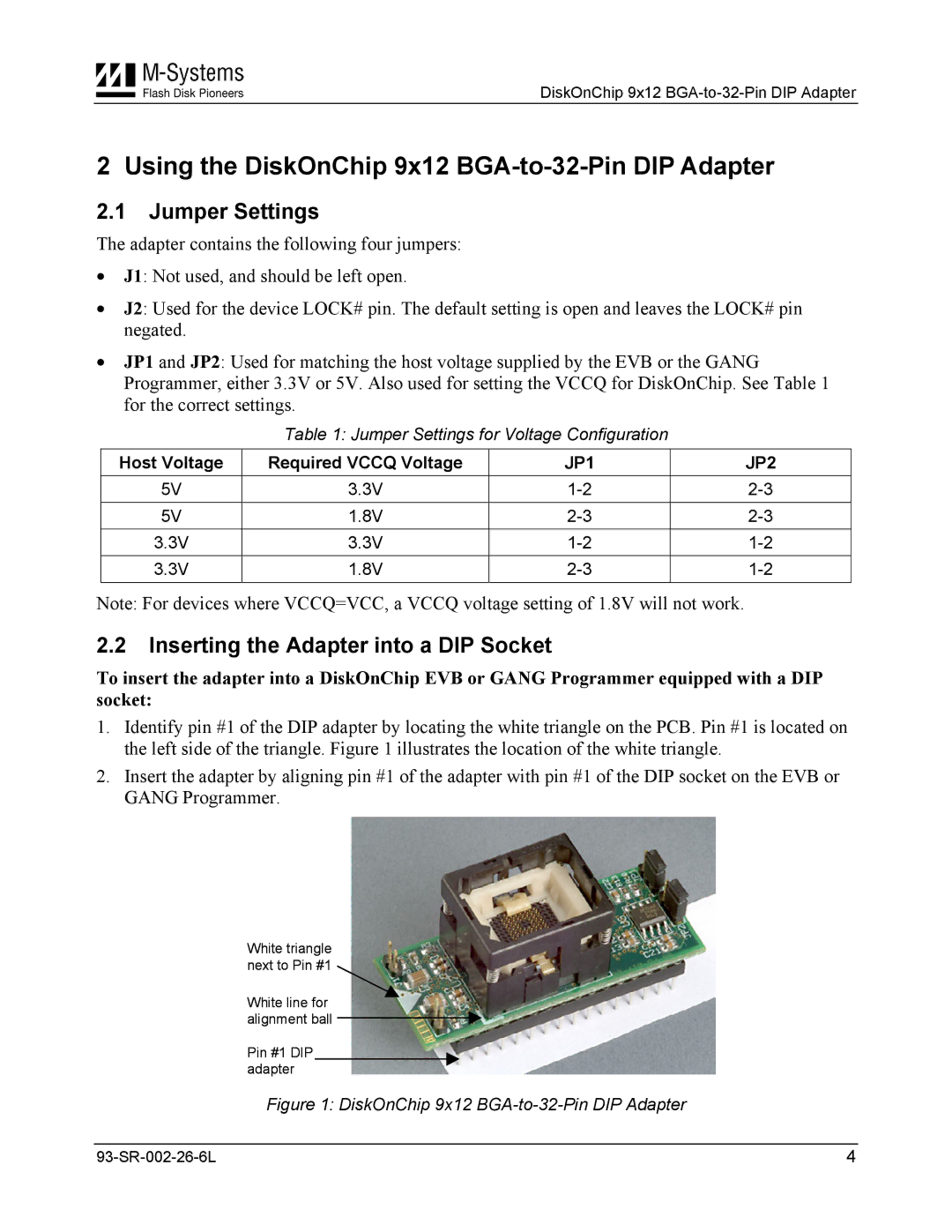
1.Identify pin #1 of the DIP adapter by locating the white triangle on the PCB. Pin #1 is located on the left side of the triangle. Figure 1 illustrates the location of the white triangle.
2.Insert the adapter by aligning pin #1 of the adapter with pin #1 of the DIP socket on the EVB or GANG Programmer.
White triangle next to Pin #1
White line for alignment ball
Pin #1 DIP adapter
Figure 1: DiskOnChip 9x12 BGA-to-32-Pin DIP Adapter
4 |