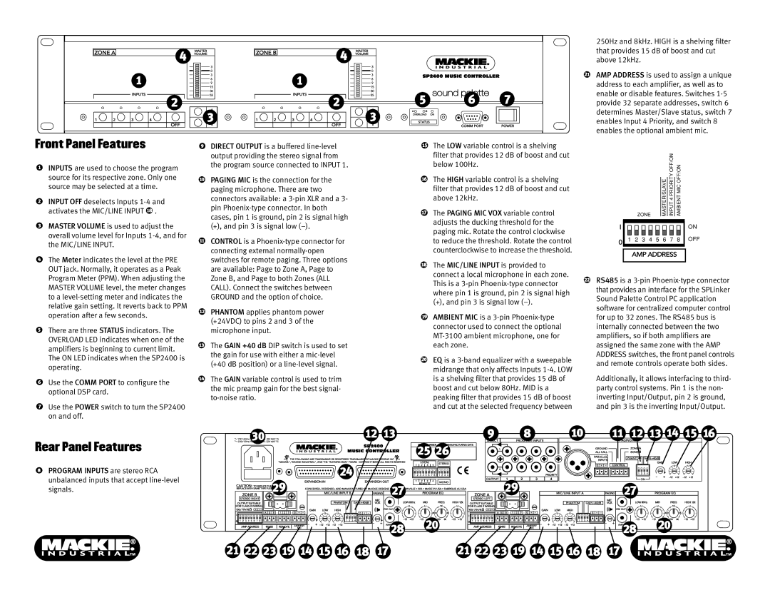
Front Panel Features
INPUTS are used to choose the program source for its respective zone. Only one source may be selected at a time.
INPUT OFF deselects Inputs ![]() .
.
MASTER VOLUME is used to adjust the overall volume level for Inputs
The Meter indicates the level at the PRE OUT jack. Normally, it operates as a Peak Program Meter (PPM). When adjusting the MASTER VOLUME level, the meter changes to a
There are three STATUS indicators. The OVERLOAD LED indicates when one of the amplifiers is beginning to current limit. The ON LED indicates when the SP2400 is operating.
Use the COMM PORT to configure the optional DSP card.
Use the POWER switch to turn the SP2400 on and off.
DIRECT OUTPUT is a buffered
PAGING MIC is the connection for the paging microphone. There are two connectors available: a
CONTROL is a
PHANTOM applies phantom power (+24VDC) to pins 2 and 3 of the microphone input.
The GAIN +40 dB DIP switch is used to set the gain for use with either a
The GAIN variable control is used to trim the mic preamp gain for the best signal-
The LOW variable control is a shelving filter that provides 12 dB of boost and cut below 100Hz.
The HIGH variable control is a shelving filter that provides 12 dB of boost and cut above 12kHz.
The PAGING MIC VOX variable control adjusts the ducking threshold for the paging mic. Rotate the control clockwise to reduce the threshold. Rotate the control counterclockwise to increase the threshold.
The MIC/LINE INPUT is provided to connect a local microphone in each zone. This is a
AMBIENT MIC is a
EQ is a
250Hz and 8kHz. HIGH is a shelving filter that provides 15 dB of boost and cut above 12kHz.
AMP ADDRESS is used to assign a unique address to each amplifier, as well as to enable or disable features. Switches
ZONE |
| MASTER/SLAVE |
| INPUT 4 PRIORITY OFF/ON |
| AMBIENT MIC OFF/ON |
|
|
|
I![]()
![]()
![]()
![]()
![]()
![]()
![]()
![]()
![]()
![]()
![]()
![]()
![]()
![]()
![]()
![]() ON
ON
01 2 3 4 5 6 7 8 OFF
AMP ADDRESS
RS485 is a
Additionally, it allows interfacing to third- party control systems. Pin 1 is the non- inverting Input/Output, pin 2 is ground, and pin 3 is the inverting Input/Output.
Rear Panel Features
PROGRAM INPUTS are stereo RCA unbalanced inputs that accept
115V 60Hz FUSE 115/T8A 220 WATTS |
230V 50Hz FUSE 230/T4A 220 WATTS |