REMOTE is a
EXPANSION IN/OUT consists of two parallel
(continued from page 1)
Audio expansion connectors are provided on the rear panel for connecting multiple SP2400s, with shared audio via balanced busing. Each of the four program input signals can be independently assigned to the balanced bus with internal assign switces. The LOCAL/REMOTE switches on the rear panel are provided for selecting either local or bus operation for each input. The paging mic and paging control signal are also carried over the expansion bus.
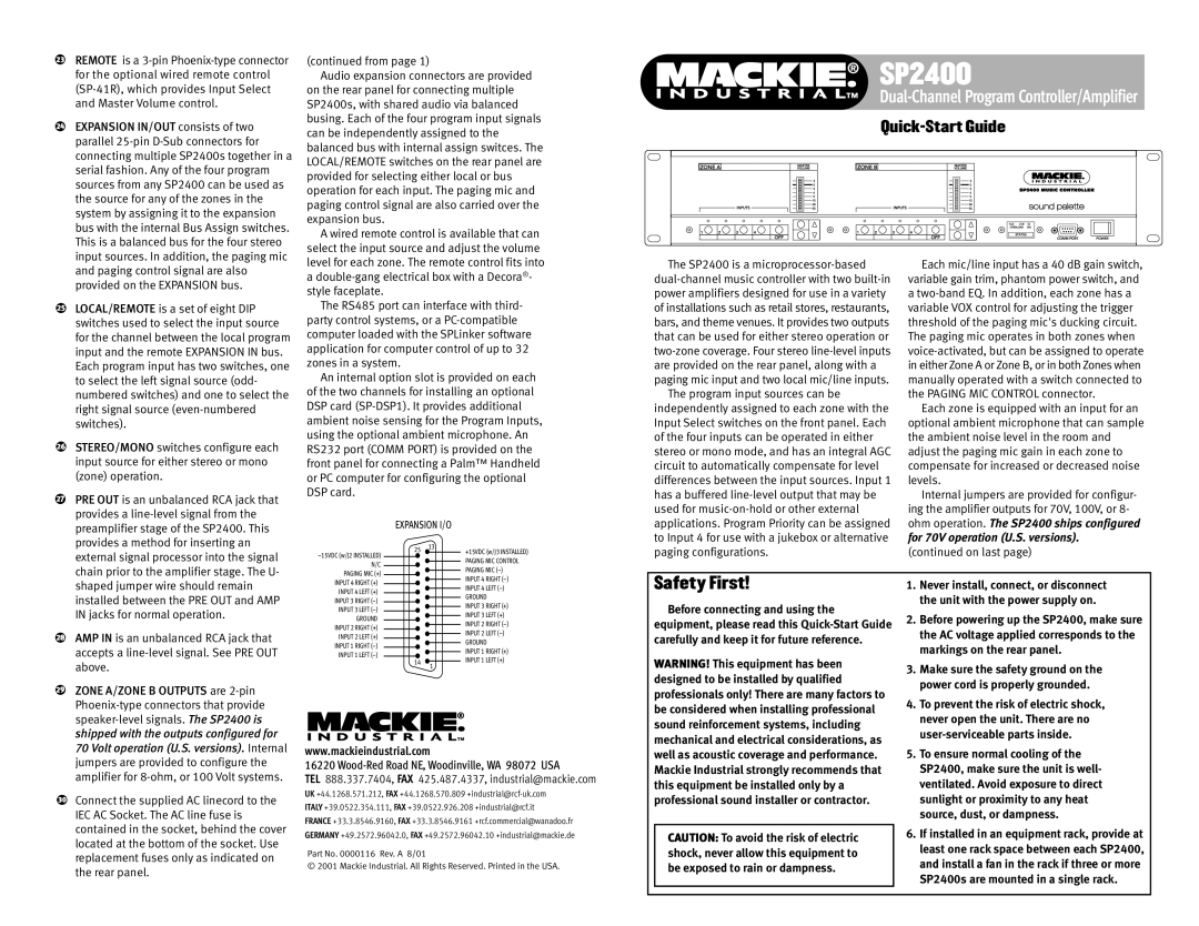
SP2400
Dual-Channel Program Controller/Amplifier
Quick-Start Guide
This is a balanced bus for the four stereo input sources. In addition, the paging mic and paging control signal are also provided on the EXPANSION bus.
LOCAL/REMOTE is a set of eight DIP switches used to select the input source for the channel between the local program input and the remote EXPANSION IN bus. Each program input has two switches, one to select the left signal source (odd- numbered switches) and one to select the right signal source
STEREO/MONO switches configure each input source for either stereo or mono (zone) operation.
PRE OUT is an unbalanced RCA jack that provides a
A wired remote control is available that can select the input source and adjust the volume level for each zone. The remote control fits into
adouble-gang electrical box with a Decora®- style faceplate.
The RS485 port can interface with third- party control systems, or a
An internal option slot is provided on each of the two channels for installing an optional DSP card
EXPANSION I/O
The SP2400 is a
The program input sources can be independently assigned to each zone with the Input Select switches on the front panel. Each of the four inputs can be operated in either stereo or mono mode, and has an integral AGC circuit to automatically compensate for level differences between the input sources. Input 1 has a buffered
Each mic/line input has a 40 dB gain switch, variable gain trim, phantom power switch, and a
Each zone is equipped with an input for an optional ambient microphone that can sample the ambient noise level in the room and adjust the paging mic gain in each zone to compensate for increased or decreased noise levels.
Internal jumpers are provided for configur- ing the amplifier outputs for 70V, 100V, or 8- ohm operation. The SP2400 ships configured for 70V operation (U.S. versions).
external signal processor into the signal chain prior to the amplifier stage. The U-
25 13
+15VDC (w/J3 INSTALLED) PAGING MIC CONTROL PAGING MIC
paging configurations.
(continued on last page)
shaped jumper wire should remain installed between the PRE OUT and AMP IN jacks for normal operation.
AMP IN is an unbalanced RCA jack that accepts a
INPUT 4 RIGHT (+) INPUT 4 LEFT (+)
INPUT 3 RIGHT
GROUND INPUT 2 RIGHT (+)
INPUT 2 LEFT (+) INPUT 1 RIGHT
INPUT 1 LEFT
14 1
INPUT 4 RIGHT
GROUND
INPUT 3 RIGHT (+) INPUT 3 LEFT (+) INPUT 2 RIGHT
GROUND
INPUT 1 RIGHT (+) INPUT 1 LEFT (+)
Safety First! | 1. | Never install, connect, or disconnect | |
Before connecting and using the |
| the unit with the power supply on. | |
2. | Before powering up the SP2400, make sure | ||
equipment, please read this | |||
| the AC voltage applied corresponds to the | ||
carefully and keep it for future reference. |
| ||
| markings on the rear panel. | ||
|
| ||
WARNING! This equipment has been | 3. | Make sure the safety ground on the | |
designed to be installed by qualified | |||
| power cord is properly grounded. |
ZONE A/ZONE B OUTPUTS are
Connect the supplied AC linecord to the IEC AC Socket. The AC line fuse is contained in the socket, behind the cover located at the bottom of the socket. Use replacement fuses only as indicated on the rear panel.
www.mackieindustrial.com
16220
TEL 888.337.7404, FAX 425.487.4337, industrial@mackie.com
UK +44.1268.571.212, FAX +44.1268.570.809
FRANCE +33.3.8546.9160, FAX +33.3.8546.9161 +rcf.commercial@wanadoo.fr GERMANY +49.2572.96042.0, FAX +49.2572.96042.10 +industrial@mackie.de
Part No. 0000116 Rev. A 8/01
© 2001 Mackie Industrial. All Rights Reserved. Printed in the USA.
professionals only! There are many factors to | 4. To prevent the risk of electric shock, | |
be considered when installing professional | ||
never open the unit. There are no | ||
sound reinforcement systems, including | ||
| ||
mechanical and electrical considerations, as | ||
| ||
well as acoustic coverage and performance. | 5. To ensure normal cooling of the | |
Mackie Industrial strongly recommends that | SP2400, make sure the unit is well- | |
this equipment be installed only by a | ventilated. Avoid exposure to direct | |
professional sound installer or contractor. | sunlight or proximity to any heat | |
| source, dust, or dampness. | |
| 6. If installed in an equipment rack, provide at | |
CAUTION: To avoid the risk of electric | ||
least one rack space between each SP2400, | ||
shock, never allow this equipment to | ||
and install a fan in the rack if three or more | ||
be exposed to rain or dampness. | ||
SP2400s are mounted in a single rack. | ||
|