in stereo. The answer to this question will also affect the location of the speakers in the room and the settings for the STEREO/MONO switches for the input sources.
3.How many program sources are going to be used? If the number of program sources is four or less, they can be centralized at one SP2400 and distributed via the Expansion Bus. If there are more than four program sources, they must be distributed among the SP2400s. Determine the number and location of the program sources that are going to be used.
Determine which program sources are going to be used for each zone, and set the LOCAL/REMOTE and internal BUS ASSIGN switches appropriately.
CAUTION: Never assign more than one program source to the same channel on the Expansion Bus.
If there is a requirement for
If there is a jukebox, use Input 4 in Program Priority mode (set the AMP ADDRESS switch #7 UP to activate). When a signal appears at Input 4 it overrides the selected Input source.
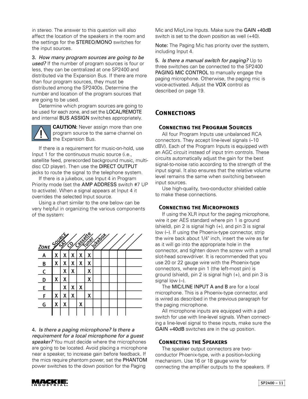
Using a chart similar to the one below can be very helpful in organizing the various components of the system:
Zone |
| SAT | CD | CassetteTunerJukebox | |
| Source |
|
|
| |
A | X | X | X | X | X |
B | X | X | X | X | X |
C |
| X | X |
| X |
D | X | X |
|
| X |
E |
| X | X | X |
|
F | X | X | X |
| X |
G | X | X |
| X |
|
4.Is there a paging microphone? Is there a requirement for a local microphone for a guest speaker? You must decide where the microphones are going to be located. Avoid placing a microphone near a speaker, to increase gain before feedback. If the mics require phantom power, set the PHANTOM
power switches to the down position for the Paging
Mic and Mic/Line Inputs. Make sure the GAIN +40dB switch is set to the down position as well (+40).
Note: The Paging Mic has priority over the system, including Input 4.
5.Is there a manual switch for paging? Up to three switches can be connected to the SP2400 PAGING MIC CONTROL to manually engage the paging microphone. Otherwise, the paging mic is
Connections
Connecting the Program Sources
All four Program Inputs use unbalanced RCA connectors. They accept
Use
Connecting the Microphones
If using the XLR input for the paging microphone, wire it per AES standard where pin 1 is ground (shield), pin 2 is signal high (+), and pin 3 is signal low
The MIC/LINE INPUT A and B are for a local microphone. This is a
All microphone inputs are equipped with a pad switch for use with
Connecting the Speakers
The speaker output connectors are two- conductor
SP2400 – 11