Vermont Castings Jefferson Vent Free Gas Heater
| 5 |
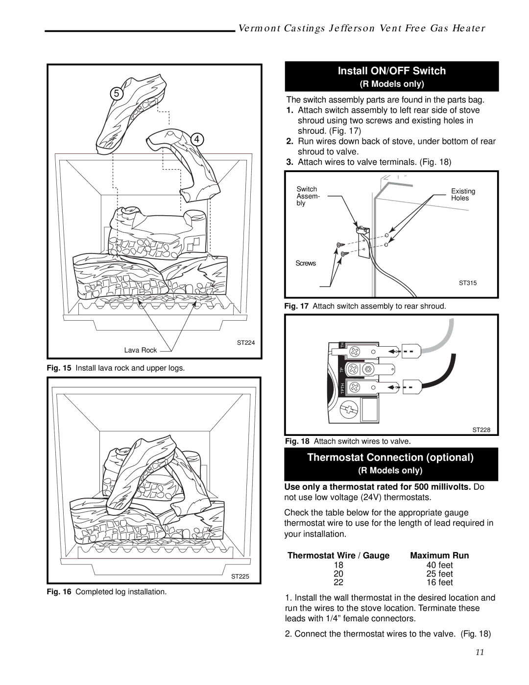
| 4 |
| ST224 |
| Lava Rock |
Fig. 15 | Install lava rock and upper logs. |
| ST225 |
Fig. 16 | Completed log installation. |
Install ON/OFF Switch
(R Models only)
The switch assembly parts are found in the parts bag.
1.Attach switch assembly to left rear side of stove shroud using two screws and existing holes in shroud. (Fig. 17)
2.Run wires down back of stove, under bottom of rear shroud to valve.
3.Attach wires to valve terminals. (Fig. 18)
Switch | Existing |
Assem- | Holes |
bly |
|
Screws |
|
| ST315 |
Fig. 17 Attach switch assembly to rear shroud. |
|
TH |
TP |
TPTH |
ST228
Fig. 18 Attach switch wires to valve.
Thermostat Connection (optional)
(R Models only)
Use only a thermostat rated for 500 millivolts. Do not use low voltage (24V) thermostats.
Check the table below for the appropriate gauge thermostat wire to use for the length of lead required in your installation.
Thermostat Wire / Gauge | Maximum Run |
18 | 40 feet |
20 | 25 feet |
22 | 16 feet |
1.Install the wall thermostat in the desired location and run the wires to the stove location. Terminate these leads with 1/4” female connectors.
2.Connect the thermostat wires to the valve. (Fig. 18)
11