I F USED AS A GRINDER
NOTE:
Use grinder accessories specified in this manual. These must be purchased by separate.
WARNING:
Always use guard assembly or accessory kit, noted below, for type 27 depressed center wheel.
Guard assembly |
| Guard accessory kit |
|
Part No. | For 180 mm (7") | Part No. | For 180 mm (7") |
Part No. | For 230 mm (9") | Part No. | For 230 mm (9") |
Installingor removingdepressed center wheel
CAUTION :
Always be sure that the tool i s switched off and unplugged before installing or removing the wheel.
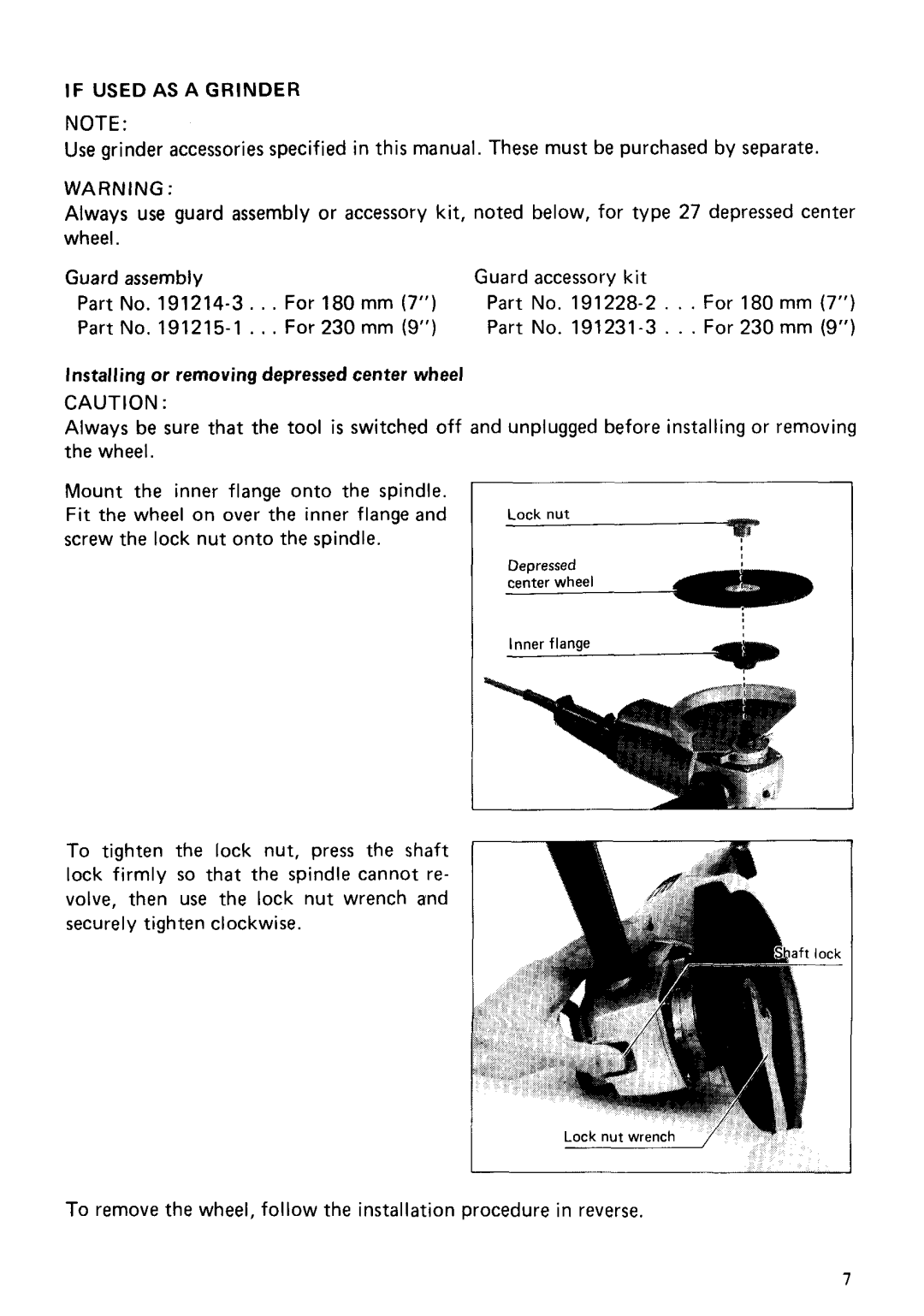
Mount the inner flange onto the spindle. Fit the wheel on over the inner flange and screw the lock nut onto the spindle.
Inner flange
To tighten the lock nut, press the shaft lock firmly so that the spindle cannot re- volve, then use the lock nut wrench and securely tighten clockwise.
To remove the wheel, follow the installation procedure in reverse.
7
