![]() WARNING:
WARNING:
MISUSE or failure to follow the safety rules stated in this instruction manual may cause serious personal injury.
Symbols
The followings show the symbols used for tool.
・volts
・amperes
・hertz
・ alternating current
・no load speed
・ Class II Construction
・ revolutions or reciprocation per minute
FUNCTIONAL DESCRIPTION
![]() CAUTION:
CAUTION:
•Always be sure that the tool is switched off and unplugged before adjusting or checking function on the tool.
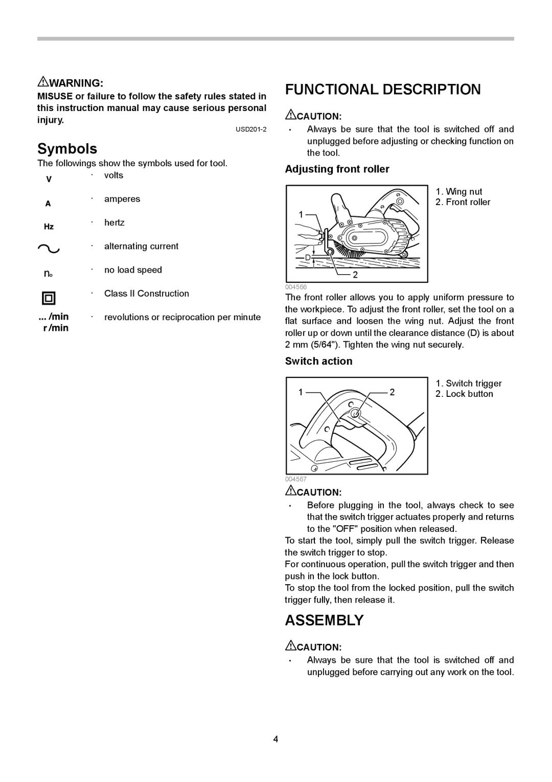
Adjusting front roller
1. Wing nut
2. Front roller
1
D
2
004566
The front roller allows you to apply uniform pressure to the workpiece. To adjust the front roller, set the tool on a flat surface and loosen the wing nut. Adjust the front roller up or down until the clearance distance (D) is about 2 mm (5/64"). Tighten the wing nut securely.
Switch action
1 | 2 | 1. | Switch trigger |
2. | Lock button | ||
|
|
|
|
004567
![]() CAUTION:
CAUTION:
•Before plugging in the tool, always check to see that the switch trigger actuates properly and returns
to the "OFF" position when released.
To start the tool, simply pull the switch trigger. Release the switch trigger to stop.
For continuous operation, pull the switch trigger and then push in the lock button.
To stop the tool from the locked position, pull the switch trigger fully, then release it.
ASSEMBLY
![]() CAUTION:
CAUTION:
•Always be sure that the tool is switched off and unplugged before carrying out any work on the tool.
4