CP 7/ 7
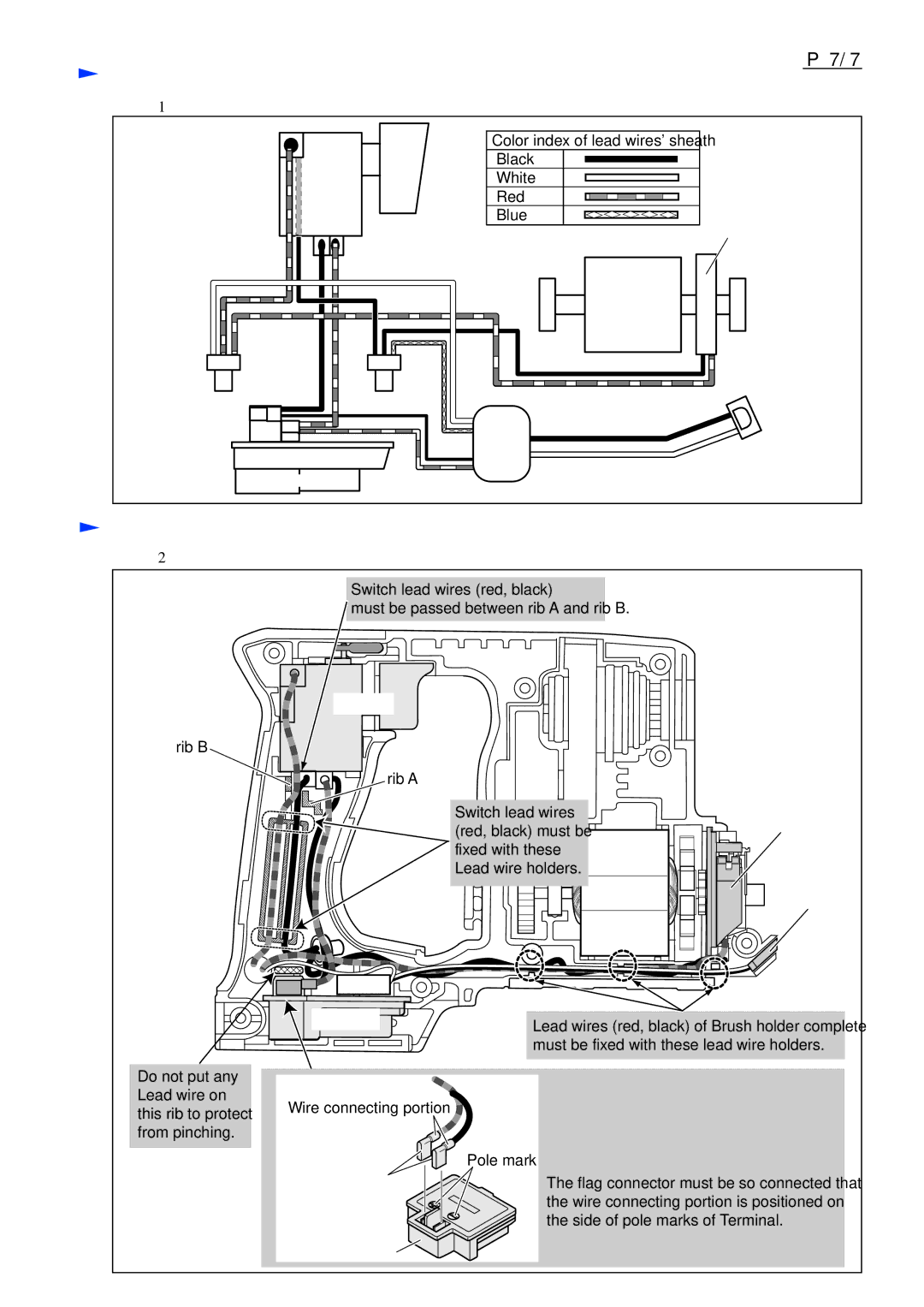
ircuit diagram Fig. D-1
Switch
Terminal
Color index of lead wires' sheath
Black
White
Red
Blue
Yoke unit
Circuit
Brush Holder Complete
![]() LED
LED
 Wiring diagram
Fig. D-2
Switch lead wires (red, black)
must be passed between rib A and rib B.
Switch
rib B
rib A
Switch lead wires (red, black) must be ![]()
![]() fixed with these
fixed with these![]()
![]()
![]()
![]()
![]()
![]() Lead wire holders.
Lead wire holders. ![]()
![]()
![]()
![]()
![]()
![]()
Brush holder complete
LED
Do not put any Lead wire on this rib to protect from pinching.
Terminal | Lead wires (red, black) of Brush holder complete | |
| ||
| must be fixed with these lead wire holders. | |
Wire connecting portion | Connecting Flag Connector | |
| ||
| to Terminal | |
Flag connector | Pole mark | |
The flag connector must be so connected that | ||
| ||
| the wire connecting portion is positioned on | |
| the side of pole marks of Terminal. | |
Terminal |
|
