P 4/ 7
 Repair
[3] DISASSEMBLY/ASSEMBLY
[3] -4. Helical Gear 48, Clutch Section (cont.)
ASSEMBLING
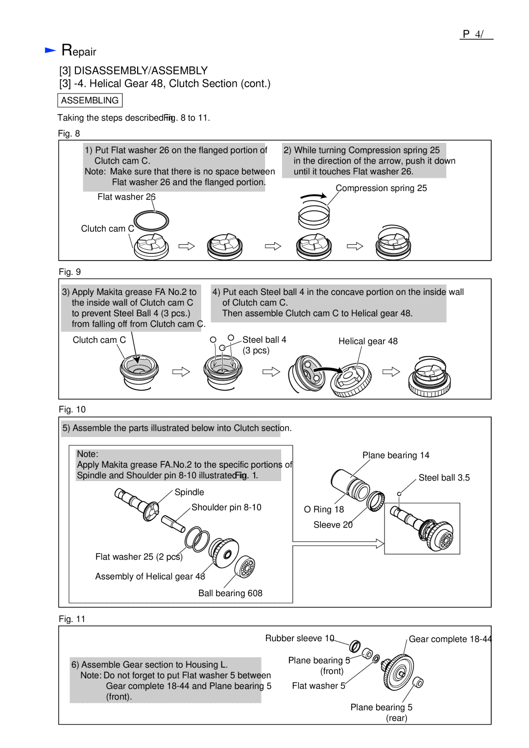
Taking the steps described in Fig. 8 to 11.
Fig. 8
1) Put Flat washer 26 on the flanged portion of | 2) While turning Compression spring 25 | |
Clutch cam C. | in the direction of the arrow, push it down | |
Note: Make sure that there is no space between | until it touches Flat washer 26. | |
Flat washer 26 and the flanged portion. | Compression spring 25 | |
Flat washer 26 | ||
| ||
Clutch cam C |
|
Fig. 9
3)Apply Makita grease FA No.2 to the inside wall of Clutch cam C to prevent Steel Ball 4 (3 pcs.) from falling off from Clutch cam C.
4)Put each Steel ball 4 in the concave portion on the inside wall of Clutch cam C.
Then assemble Clutch cam C to Helical gear 48.
Clutch cam C | Steel ball 4 | Helical gear 48 |
| (3 pcs) |
|
Fig. 10
5) Assemble the parts illustrated below into Clutch section.
Note:
Apply Makita grease FA.No.2 to the specific portions of Spindle and Shoulder pin
Spindle
Shoulder pin
Flat washer 25 (2 pcs) ![]()
Assembly of Helical gear 48 ![]()
Ball bearing 608
Plane bearing 14
Steel ball 3.5
O Ring 18
Sleeve 20
Fig. 11
| Rubber sleeve 10 | Gear complete |
6) Assemble Gear section to Housing L. | Plane bearing 5 |
|
(front) |
| |
Note: Do not forget to put Flat washer 5 between |
| |
|
| |
Gear complete | Flat washer 5 |
|
(front). |
|
|
|
| Plane bearing 5 |
|
| (rear) |
