 Wiring diagram
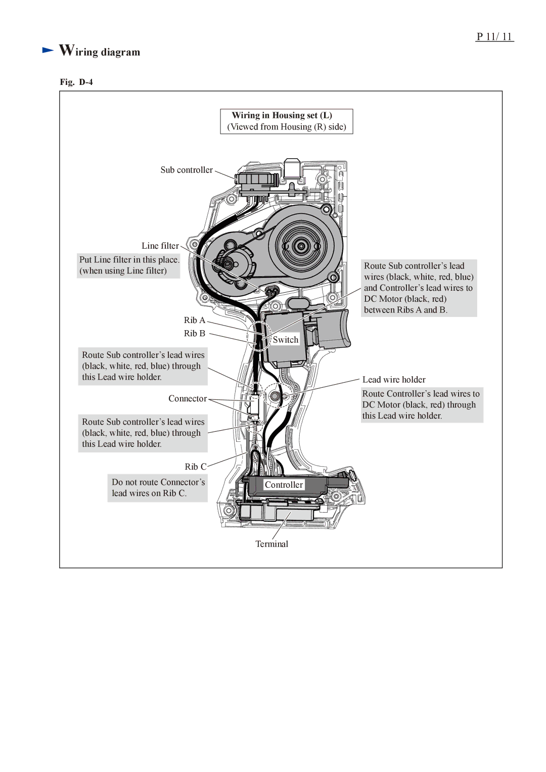
Fig. D-4
P 11/ 11
Wiring in Housing set (L) (Viewed from Housing (R) side)
Sub controller
Line filter
Put Line filter in this place. (when using Line filter)
Rib A |
|
Rib B | Switch |
| |
Route Sub controller’s lead wires |
|
(black, white, red, blue) through |
|
this Lead wire holder. |
|
Connector |
|
Route Sub controller’s lead wires |
|
(black, white, red, blue) through |
|
this Lead wire holder. |
|
Rib C |
|
Do not route Connector’s | Controller |
lead wires on Rib C. |
|
| Terminal |
Route Sub controller’s lead wires (black, white, red, blue) and Controller’s lead wires to DC Motor (black, red) between Ribs A and B.
Lead wire holder
Route Controller’s lead wires to DC Motor (black, red) through this Lead wire holder.
