Repair
P 8/ 11
[3] DISASSEMBLY/ASSEMBLY
[3] -2. Motor Complete, Gear Assembly (cont.)
ASSEMBLING
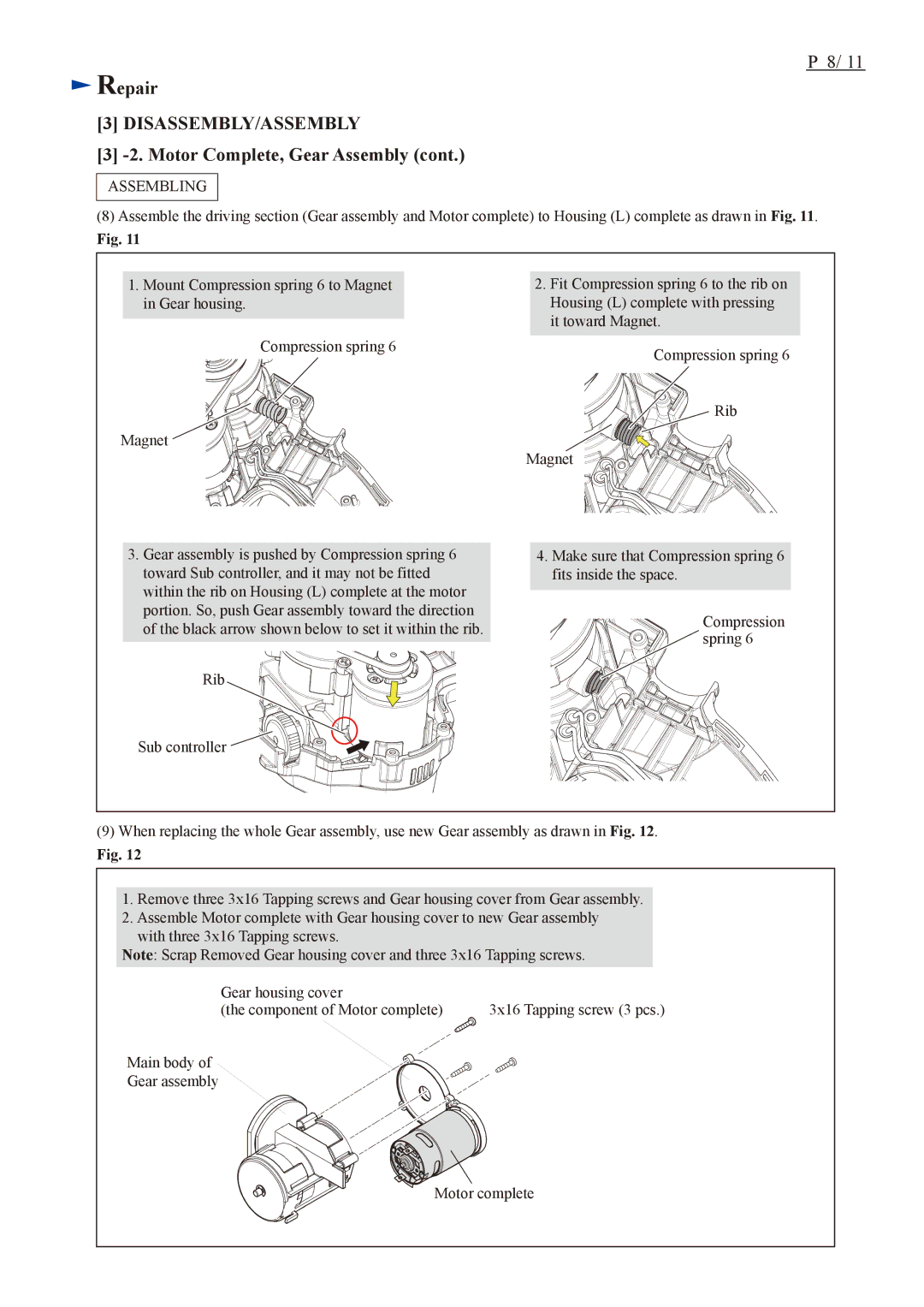
(8)Assemble the driving section (Gear assembly and Motor complete) to Housing (L) complete as drawn in Fig. 11.
Fig. 11
1.Mount Compression spring 6 to Magnet in Gear housing.
2.Fit Compression spring 6 to the rib on Housing (L) complete with pressing it toward Magnet.
Compression spring 6 | Compression spring 6 |
| |
| Rib |
Magnet | Magnet |
|
3.Gear assembly is pushed by Compression spring 6 toward Sub controller, and it may not be fitted within the rib on Housing (L) complete at the motor portion. So, push Gear assembly toward the direction of the black arrow shown below to set it within the rib.
Rib
Sub controller ![]()
![]()
![]()
![]()
![]()
![]()
![]()
![]()
![]()
![]()
![]()
![]()
![]()
![]()
![]()
![]()
![]()
![]()
![]()
![]()
![]()
![]()
![]()
![]()
![]()
4.Make sure that Compression spring 6 fits inside the space.
![]()
![]()
![]()
![]()
![]()
![]()
![]()
![]()
![]()
![]() Compression
Compression ![]()
![]()
![]()
![]() spring 6
spring 6
(9)When replacing the whole Gear assembly, use new Gear assembly as drawn in Fig. 12.
Fig. 12
1.Remove three 3x16 Tapping screws and Gear housing cover from Gear assembly.
2.Assemble Motor complete with Gear housing cover to new Gear assembly with three 3x16 Tapping screws.
Note: Scrap Removed Gear housing cover and three 3x16 Tapping screws.
Gear housing cover |
|
(the component of Motor complete) | 3x16 Tapping screw (3 pcs.) |
Main body of
Gear assembly
Motor complete