
CC9100 specifications
The Marantz CC9100 is a high-fidelity CD changer that epitomizes advanced audio technology and elegant design. Released by the legendary audio equipment manufacturer Marantz, known for its dedication to quality and performance, the CC9100 is a hallmark of versatility and modern engineering.One of the standout features of the CC9100 is its ability to hold and play up to 300 CDs, making it an ideal choice for audiophiles with extensive music collections. The multi-disc capability allows users to seamlessly transition between albums and playlists without the need to manually swap discs. This feature is particularly beneficial for parties or extended listening sessions, where having a variety of music readily available enhances the experience.
The CC9100 also boasts a sophisticated digital-to-analog converter (DAC) that ensures high-quality sound reproduction. This DAC is crucial for delivering clarity, detail, and a more engaging listening experience, as it converts digital audio signals into analog sound that our ears can perceive. Additionally, the unit supports various audio formats, allowing users to enjoy their favorite music in different ways.
Moreover, the Marantz CC9100 incorporates a user-friendly interface and a well-organized display, making navigation through extensive music libraries a breeze. The remote control functionality provides added convenience, enabling users to change tracks, adjust volumes, and switch between different playlists without leaving their seats.
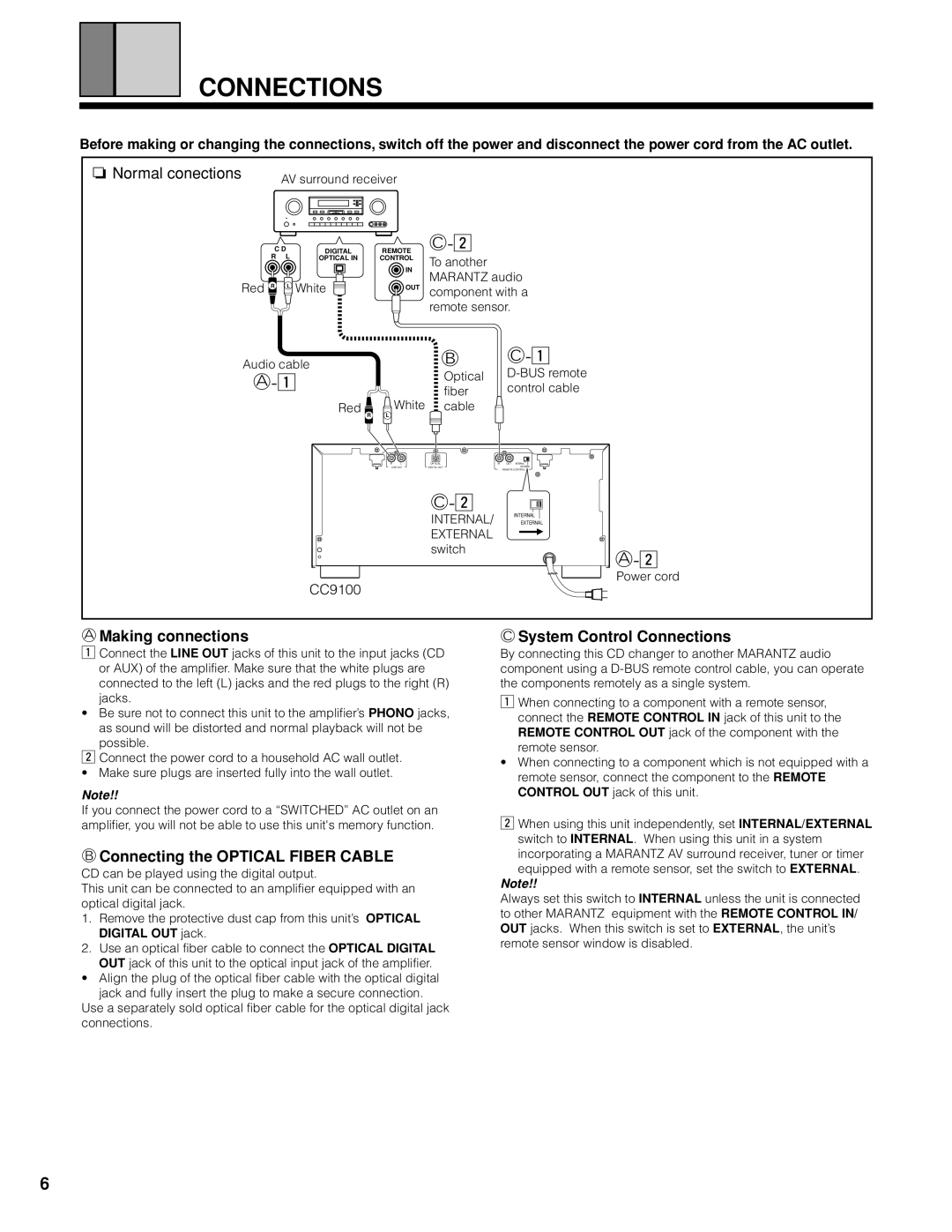
For those who seek connectivity, the CC9100 includes analog outputs, ensuring compatibility with a wide range of audio systems and setups. This flexibility allows it to integrate seamlessly into both modern and traditional audio environments, thus catering to diverse preferences.
Another commendable characteristic of the CC9100 is its sturdy construction and elegant design. Built with high-quality materials, the unit not only withstands the rigors of daily use but also adds a touch of sophistication to any audio setup. The attention to detail in its aesthetics ensures that the CC9100 is more than just a functional device; it’s a statement piece for any music lover.
In summary, the Marantz CC9100 is a robust and feature-rich CD changer that combines performance, convenience, and style. Its vast storage capacity, high-quality DAC, user-friendly interface, and elegant design make it a top choice for anyone looking to elevate their audio experience. Whether you’re a dedicated audiophile or simply someone who appreciates great music, the CC9100 stands ready to deliver exceptional sound quality and usability.