ENGLISH
SUPPLIED ACCESSORIES
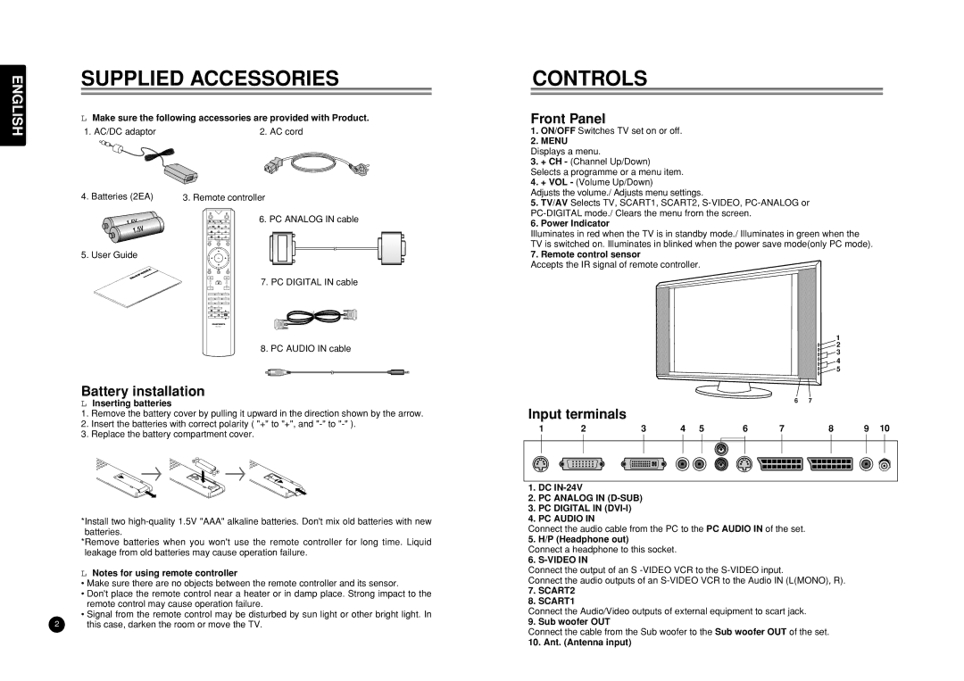
LMake sure the following accessories are provided with Product.
1. AC/DC adaptor | 2. AC cord |
4. | Batteries (2EA) | 3. Remote controller | |||
|
|
| P P | R | 6. PC ANALOG IN cable |
|
| LIST |
| G |
|
|
|
|
| Y |
|
|
|
|
| B |
|
|
| TV/AV | TV/PC | MENU |
|
5. | User Guide |
| OK |
|
|
| MUTE |
| 7. PC DIGITAL IN cable | |||
CH |
| VOL. |
|
|
|
|
1 | 2 | 3 |
|
|
|
|
4 | 5 | 6 |
|
|
|
|
7 | 8 | 9 |
|
|
|
|
PIP | 0 |
|
|
|
|
|
|
|
|
|
|
|
|
|
|
|
|
|
|
|
CH
8. PC AUDIO IN cable
Battery installation
LInserting batteries
1.Remove the battery cover by pulling it upward in the direction shown by the arrow.
2.Insert the batteries with correct polarity ( "+" to "+", and
3.Replace the battery compartment cover.
 →
→ 


 →
→ 
*Install two
*Remove batteries when you won't use the remote controller for long time. Liquid leakage from old batteries may cause operation failure.
LNotes for using remote controller
•Make sure there are no objects between the remote controller and its sensor.
•Don't place the remote control near a heater or in damp place. Strong impact to the remote control may cause operation failure.
•Signal from the remote control may be disturbed by sun light or other bright light. In
2 this case, darken the room or move the TV.
CONTROLS
Front Panel
1.ON/OFF Switches TV set on or off.
2.MENU
Displays a menu.
3.+ CH - (Channel Up/Down) Selects a programme or a menu item.
4.+ VOL - (Volume Up/Down)
Adjusts the volume./ Adjusts menu settings.
5.TV/AV Selects TV, SCART1, SCART2,
6.Power Indicator
Illuminates in red when the TV is in standby mode./ Illuminates in green when the TV is switched on. Illuminates in blinked when the power save mode(only PC mode).
7. Remote control sensor
Accepts the IR signal of remote controller.
1 ![]()
![]() 2
2 ![]() 3
3
4
![]()
![]() 5
5
6 7
Input terminals
1 | 2 | 3 |
| 4 | 5 | 6 |
| 7 | 8 | 9 | 10 | |||||||||||||||||
|
|
|
|
|
|
|
|
|
|
|
|
|
|
|
|
|
|
|
|
|
|
|
|
|
|
|
|
|
|
|
|
|
|
|
|
|
|
|
|
|
|
|
|
|
|
|
|
|
|
|
|
|
|
|
|
|
|
|
|
|
|
|
|
|
|
|
|
|
|
|
|
|
|
|
|
|
|
|
|
|
|
|
|
|
|
|
|
|
|
|
|
|
|
|
|
|
|
|
|
|
|
|
|
|
|
|
|
|
|
|
|
|
|
|
|
1.DC
2.PC ANALOG IN (D-SUB)
3.PC DIGITAL IN (DVI-I)
4.PC AUDIO IN
Connect the audio cable from the PC to the PC AUDIO IN of the set.
5. H/P (Headphone out)
Connect a headphone to this socket.
6. S-VIDEO IN
Connect the output of an S
Connect the audio outputs of an
7.SCART2
8.SCART1
Connect the Audio/Video outputs of external equipment to scart jack.
9. Sub woofer OUT
Connect the cable from the Sub woofer to the Sub woofer OUT of the set.
10. Ant. (Antenna input)
