Operation
1.After power has been connected to unit, fans will start in either preset (high/low) speed selection.
2.Air velocity is controlled by selection of high or low speed indicator. This feature allows the setting of air velocity to individual desired performance and energy efficiency.
3.Air direction at outlet can be controlled by adjustable vanes at the nozzle which compensates for possible draft conditions.
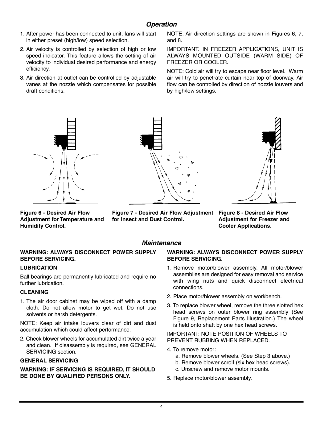
NOTE: Air direction settings are shown in Figures 6, 7, and 8.
IMPORTANT. IN FREEZER APPLICATIONS, UNIT IS ALWAYS MOUNTED OUTSIDE (WARM SIDE) OF FREEZER OR COOLER.
NOTE: Cold air will try to escape near floor level. Warm air will try to penetrate curtain near top of doorway. Air flow can be controlled by direction of nozzle louvers and by high/low settings.
Figure 6 - Desired Air Flow Adjustment for Temperature and Humidity Control.
Figure 7 - Desired Air Flow Adjustment for Insect and Dust Control.
Figure 8 - Desired Air Flow Adjustment for Freezer and Cooler Applications.
Maintenance
WARNING: ALWAYS DISCONNECT POWER SUPPLY BEFORE SERVICING.
LUBRICATION
Ball bearings are permanently lubricated and require no further lubrication.
CLEANING
1.The air door cabinet may be wiped off with a damp cloth. Do not allow motor to get wet. Do not use solvents or harsh detergents.
NOTE: Keep air intake louvers clear of dirt and dust accumulation which could affect performance.
2.Check blower wheels for accumulated dirt twice a year and clean. If disassembly is required, see GENERAL SERVICING section.
GENERAL SERVICING
WARNING: IF SERVICING IS REQUIRED, IT SHOULD BE DONE BY QUALIFIED PERSONS ONLY.
WARNING: ALWAYS DISCONNECT POWER SUPPLY BEFORE SERVICING.
1.Remove motor/blower assembly. All motor/blower assemblies are designed for easy removal and service with wing nuts and quick disconnect electrical connections.
2.Place motor/blower assembly on workbench.
3.To replace blower wheel, remove the three slotted hex head screws on outer blower ring assembly (See Figure 9, Replacement Parts Illustration.) The wheel is held onto shaft by one hex head screws.
IMPORTANT: NOTE POSITION OF WHEELS TO PREVENT RUBBING WHEN REPLACED.
4.To remove motor:
a.Remove blower wheels. (See Step 3 above.)
b.Remove blower scrolI (six hex head screws).
c.Unscrew and remove motor mounts.
5.Replace motor/blower assembly.
4