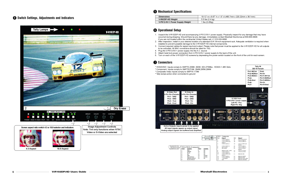
8Switch Settings, Adjustments and Indicators
Tally Lamps
V-R102P-HD
 Dry Erase
Screen aspect ratio switch 4:3 or 16:9 selector and indicators | Image Adjustment Controls | ||
|
|
| Note: Tint only functions when NTSC |
|
|
| |
|
|
| Video or |
|
|
| |
|
|
|
|
5Mechanical Specifications
Dimensions | 19.12” w x 8.67” h x 1.5” d (485.7mm x 220.22mm x 38.1mm) |
5.5 lbs (2.4 kg) | |
1 lbs (0.45kg) |
6Operational Setup
1.Unpack the
If you are not located within the continental United States call +1
2.After inspection, install in your desired location of a standard EIA
3.Connect required cables for signal input and output. Please note that power must be applied to the
4.Plug the
5.Attach twist lock power connection from
6.Turn on each of the
7Connectors
* HDSDI/SDI Inputs comply to |
|
| Tally IN | |||||||
* Component Inputs comply to SMPTE274M, 294M,295M,296M |
|
|
| |||||||
|
|
|
| Pin9- | ||||||
* Composite Video Inputs comply to |
|
|
|
| ||||||
* Tally lamps active when connected to ground |
|
|
|
| Pin10- | |||||
|
|
|
|
|
|
|
|
| ||
|
|
|
|
|
|
|
| Pin4- |
| |
|
|
|
|
|
|
|
|
| ||
|
|
|
|
|
|
|
| Pin6- |
| Pin14- |
|
|
|
|
|
|
|
| Pin7- |
| |
|
|
|
|
|
|
|
|
|
|
|
|
|
|
|
|
|
|
|
|
|
|
|
|
|
|
|
| |||||
| 4 Pin Din (Female) |
| 4 Pin Din (Female) |
|
|
|
|
|
|
|
| Pin1 - GND |
| Pin1 - GND |
|
|
|
|
|
|
|
| Pin2 - GND |
| Pin2 - GND |
| 12 VDC from |
|
|
| ||
| Pin3 - Yout |
| Pin3 - Yin |
|
|
|
| |||
| Pin4 - Cout |
| Pin4 - Cin |
| Left Pin - Pos |
|
|
| ||
|
|
|
|
| Right Pin- Neg |
|
|
| ||
|
|
|
|
|
|
|
| |||
Active Outputs require power to be applied
All input signals appear as output signal
Analog output signals are buffered and amplified
Pin# | Signal | Pin# | Signal |
4:3 Aspect | 16:9 Aspect |
VGA/XGA Connector
PIN# | SIGNAL | PIN# | SIGNAL |
1 | RED | 9 | NC |
2 | GREEN | 10 | NC |
3 | BLUE | 11 | NC |
4 | NC | 12 | NC |
5 | GND | 13 | HSYNC |
6 | RED SHIELD | 14 | VSYNC |
7 | GREEN SHIELD | 15 | NC |
8 | BLUE SHIELD |
|
|
1 | T.M.D.S DATA 2- | 16 | HOT PLUG DETECT |
2 | T.M.D.S DATA 2+ | 17 | T.M.D.S DATA 0- |
3 | T.M.D.S DATA 2/4 | 18 | T.M.D.S DATA 0+ |
| SHIELD |
|
|
4 | T.M.D.S DATA 4- | 19 | T.M.D.S DATA 0/5 |
|
|
| SHIELD |
5 | T.M.D.S DATA 4+ | 20 | T.M.D.S DATA 5- |
6 | DDC CLOCK | 21 | T.M.D.S DATA 5+ |
7 | DDC DATA | 22 | T.M.D.S CLOCK |
|
|
| SHIELD |
8 | ANALOG VERT. SYNC | 23 | T.M.D.S CLOCK+ |
9 | T.M.D.S DATA 1- | 24 | T.M.D.S CLOCK- |
10 | T.M.D.S DATA 1+ |
|
|
11 | T.M.D.S DATA 1/3 | C1 | ANALOG RED |
| SHIELD |
|
|
12 | T.M.D.S DATA 3- | C2 | ANALOG GREEN |
13 | T.M.D.S DATA 3+ | C3 | ANALOG BLUE |
14 | +5V POWER | C4 | ANALOG HORZ SYNC |
15 | GND | C5 | ANALOG GROUND |
6 |
|
| MarshallElectronics |
| 3 | |
|
|
| ||||
|
|
|
|
|
|
|