Rear Panel Features
|
|
|
|
|
|
|
|
|
|
|
|
|
|
|
|
|
|
|
|
|
|
|
|
|
|
|
|
|
|
|
|
|
|
|
|
|
|
|
|
IN OUT | IN OUT | IN OUT |
| ||||
|
|
|
|
|
|
|
|
|
|
|
|
|
|
|
|
|
|
|
|
|
|
|
|
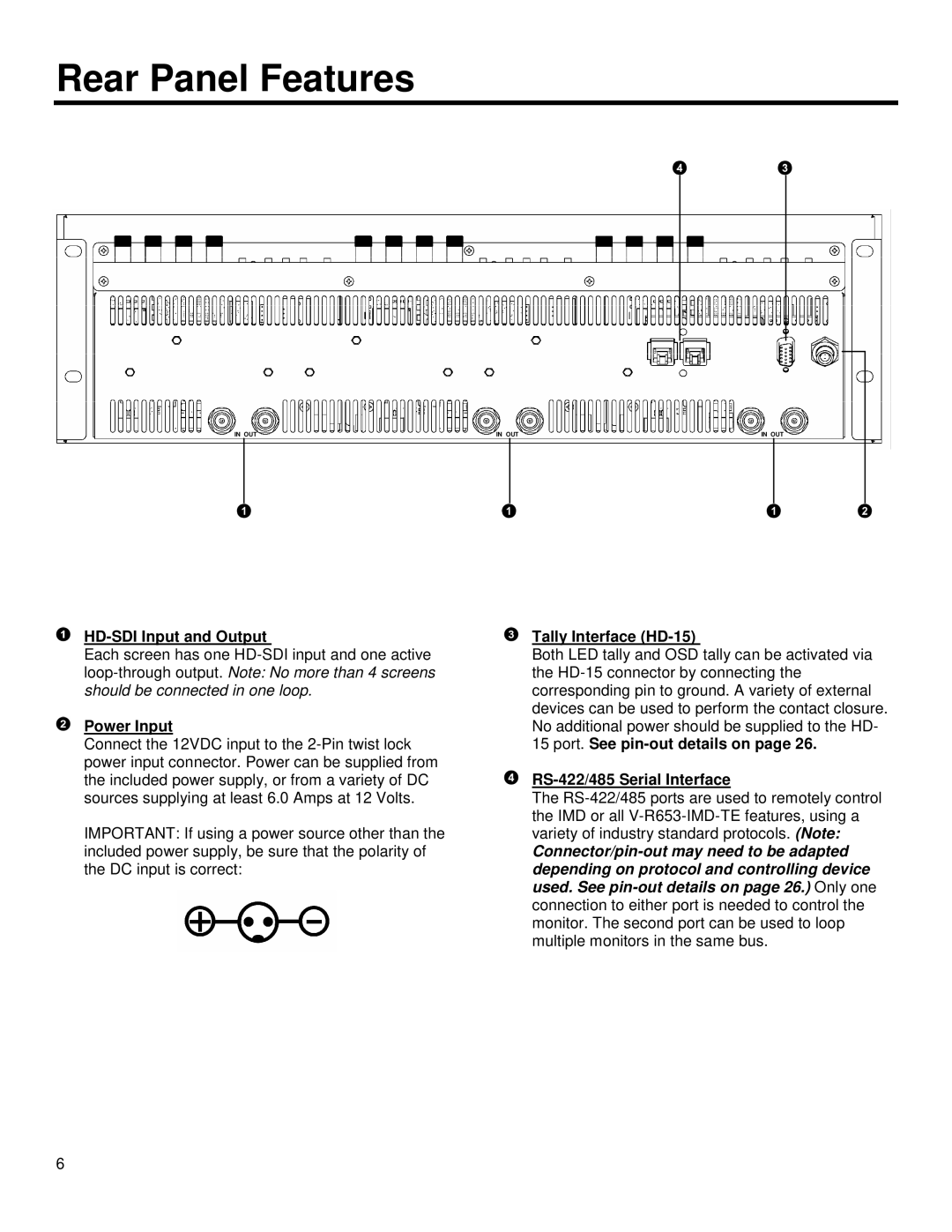
HD-SDI Input and Output
Each screen has one
Power Input
Connect the 12VDC input to the
IMPORTANT: If using a power source other than the included power supply, be sure that the polarity of the DC input is correct:
Tally Interface (HD-15)
Both LED tally and OSD tally can be activated via the
15port. See pin-out details on page 26.
RS-422/485 Serial Interface
The
6