8Operational Setup
1.Unpack the
2.Connect required cables for signal input and output.
Please note that power must be applied to the
3.Plug the
Please note that power can be supplied from a variety of DC sources, such as batteries or Vehicle power. Input power range is 10.7 to 15 Volt D.C. In operation, the
Attach twist lock power connection from
4.Turn on the
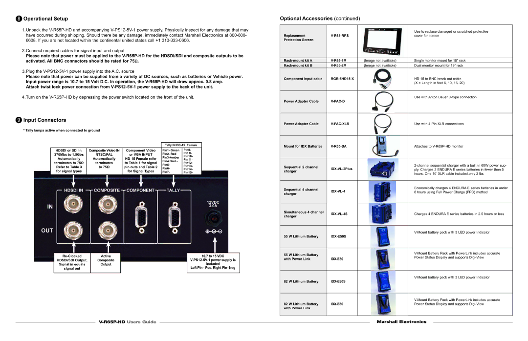
9Input Connectors
* Tally lamps active when connected to ground
Tally IN
HDSDI or SDI in. | Composite Video IN | Component Video | Pin1- Green | Pin8- | |
270Mbs to 1.5Gbs | NTSC/PAL | or VGA INPUT | Pin2- Red | Pin 9- | |
Pin10- | |||||
Automatically | Automatically | ||||
Pin11- | |||||
Pin4 Gnd - | |||||
terminates to 75Ω | terminates | to Table 1 for signal | Pin12- | ||
Pin5- | |||||
Refer to Table 3 | to 75Ω | pin outs and Table 2 | Pin13- | ||
Pin6- | |||||
Pin14- | |||||
for signal types |
| for Signal Types | |||
| Pin7- | ||||
| Pin15- | ||||
|
|
|
| Active |
| 10.7 to 15 VDC |
HDSDI/SDI Output. | Composite |
| |
Signal in equals | Output |
| included |
signal out |
|
| Left Pin - Pos. Right Pin- Neg |
|
|
|
|
Optional Accessories (continued)
|
| Use to replace damaged or scratched protective |
Replacement | cover for screen | |
Protection Screen |
|
|
(Image not available) | Single monitor mount for 19” rack | ||
(Image not available) | Dual monitor mount for 19” rack | ||
Component input cable |
|
| |
|
|
| (X = Length in feet 6, 10, 15, 20) |
|
|
|
|
|
|
| Use with Anton Bauer |
Power Adapter Cable |
|
| |
|
|
|
|
Power Adapter Cable |
|
| Use with 4 Pin XLR connections |
|
|
|
|
Mount for IDX Batteries |
| Attaches to | |
|
|
|
|
Sequential 2 channel |
|
| |
| ply. Charges 2 ENDURA E series batteries in fewer than 5 | ||
charger |
| ||
|
| hours. One 10’ XLR cable included.only 2 lbs | |
|
|
| |
|
|
|
|
Sequential 4 channel |
|
| Economically charges 4 ENDURA E series batteries in under |
| 6 hours using Full Power Charge (FPC) method | ||
charger |
| ||
|
|
| |
|
|
|
|
Simultaneous 4 channel |
|
| Charges 4 ENDURA E series batteries in 2.5 hours or less |
charger |
| ||
|
|
| |
|
|
|
|
|
|
| |
55 W Lithium Battery |
|
|
|
|
|
|
|
55 W Lithium Battery |
|
| |
|
| Power Status Display and supports | |
with Power Link |
| ||
|
| ||
|
|
|
|
|
|
| |
82 W Lithium Battery |
|
| |
|
|
|
|
|
|
| |
82 W Lithium Battery |
| Power Status Display and supports | |
with Power Link |
|
|
|
| Marshall Electronics | |
| ||
|
|
|
|
|
|