Manuals
/
Martin Audio
/
Home Audio
/
Stereo Amplifier
Martin Audio
MA1.3s 5.1.1Gain, Sensitivity, 5.1.3Options, Stereo mode, English, Contents, Print
Models:
MA1.3s
1
6
19
19
Download
19 pages
32.46 Kb
3
4
5
6
7
8
9
10
Page 6
Image 6
Page 5
Page 7
Page 6
Image 6
Page 5
Page 7
Contents
ENGLISH
CONTENTS
Martin Audio - MA1.3s Amplifier
PRINT
CONTENTS
2 APPROVALS
3 WARNINGS
Martin Audio - MA1.3s Amplifier
3.5.3Radio interference
3.5.1Loudspeaker damage
3.5.2Loudspeaker output hazard
CONTENTS
5. Signal present indicator
3. Protect indicator LED
4. Clip/limit indicator
6. On indicator
1. Output / Speaker connector
5 REAR PANEL FEATURES
8. Power switch
2. Clip limiter switch
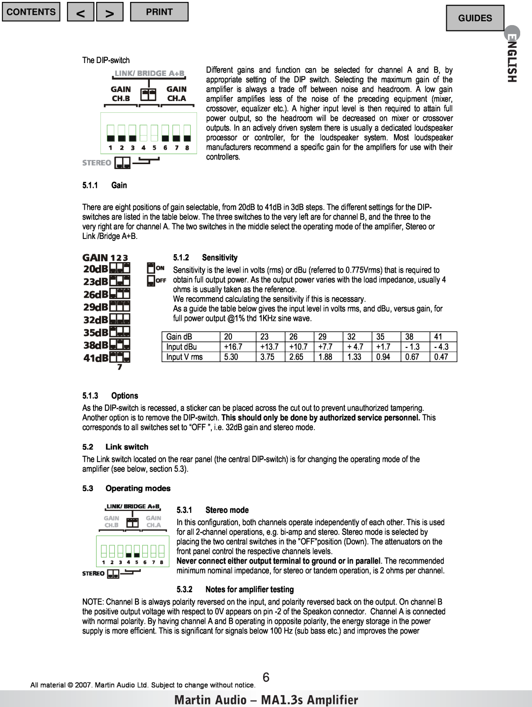
5.1.2 Sensitivity
5.3.2Notes for amplifier testing
5.1.1Gain
5.1.3Options
5.3.4Bridge mono mode
5.3.5 Bridge mono mode features
5.3.3Tandem mode
CONTENTS
LIVE
6 INSTALLATION
BLACK or BROWN
WHITE or BLUE
CONTENTS
Never disconnect lift the mains safety earth
MAX OUTPUT POWER
Martin Audio - MA1.3s Amplifier
7.1.1Balanced inputs
MA1.3s HEAT POWER
7 CONNECTIONS
CONTENTS
Martin Audio - MA1.3s Amplifier
7.1.2Unbalanced inputs
CONTENTS
ENGLISH
Martin Audio - MA1.3s Amplifier
8 OPERATION
CONTENTS
ENGLISH
Martin Audio - MA1.3s Amplifier
9 PROTECTION FEATURES
CONTENTS
ENGLISH
CONTENTS
10 MAINTENANCE
Fault No output
Martin Audio - MA1.3s Amplifier
International
11 WARRANTY
Technical assistance and services
General
POWER REQUIREMENTS
SPECIFICATIONS MA1.3S
MAXIMUM OUTPUT POWER
DIMENSIONS WEIGHT
Front Panel
SHIPPING DIMENSIONS
SHIPPING WEIGHT
Rear Panel
CONTENTS
MA1.3s Amplifier
The Martin Experience
Please Click here to return to main menu
ENGLISH
CONTENTS
User’s Guide
MA1.3s Amplifier
Top
Page
Image
Contents