|
|
| 14 |
|
|
| P |
|
| A |
|
|
|
| K |
|
|
| 11 |
|
|
| E |
23 | M | N |
|
|
| ||
|
| C | 22 |
|
| 24 25 | |
|
|
|
G
19
C
N
M
J
10
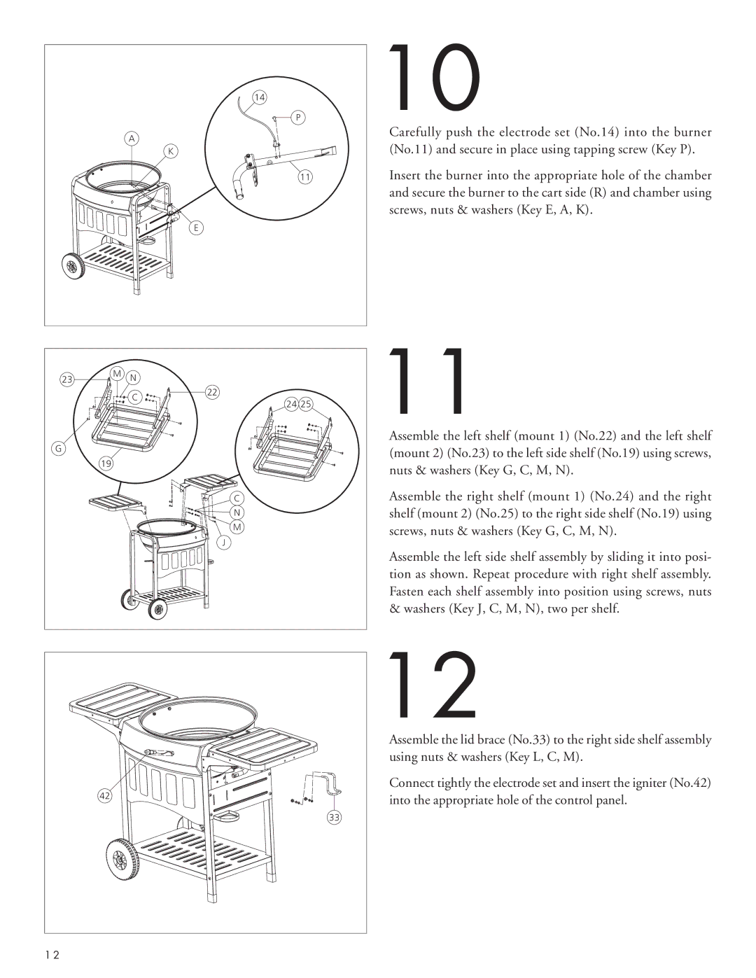
Carefully push the electrode set (No.14) into the burner (No.11) and secure in place using tapping screw (Key P).
Insert the burner into the appropriate hole of the chamber and secure the burner to the cart side (R) and chamber using screws, nuts & washers (Key E, A, K).
11
Assemble the left shelf (mount 1) (No.22) and the left shelf (mount 2) (No.23) to the left side shelf (No.19) using screws, nuts & washers (Key G, C, M, N).
Assemble the right shelf (mount 1) (No.24) and the right shelf (mount 2) (No.25) to the right side shelf (No.19) using screws, nuts & washers (Key G, C, M, N).
Assemble the left side shelf assembly by sliding it into posi- tion as shown. Repeat procedure with right shelf assembly. Fasten each shelf assembly into position using screws, nuts & washers (Key J, C, M, N), two per shelf.
42 |
33 |
1 2 |
12
Assemble the lid brace (No.33) to the right side shelf assembly using nuts & washers (Key L, C, M).
Connect tightly the electrode set and insert the igniter (No.42) into the appropriate hole of the control panel.
