Master Lock 
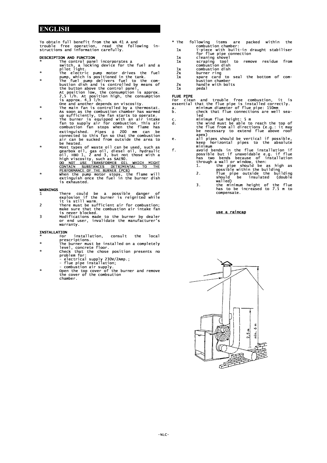
WA 59 A, WA 41 A English, Description And Function, Warnings, Installation, Flue Pipe

Models: WA 41 A WA 59 A

1 14
Download 14 pages 18.84 Kb
Page 3
Image 3
ENGLISH

ENGLISH

To obtain full benefit from the WA 41 A and

trouble free operation, read the following in- structions and information carefully.

DESCRIPTION AND FUNCTION

*The control panel incorporates a

switch, a locking device for the fuel and a pilot light.

*The electric pump motor drives the fuel pump, which is positioned in the tank.

*The fuel pump delivers fuel to the com- bustion dish and is controlled by means of the button above the control panel,

At position low, the consumption is approx. 2,5 l/h. At position high, the consumption is approx. 4,3 l/h.

One and another depends on viscosity.

*The main fan is controlled by a thermostat. As soon as the combustion chamber has warmed up sufficiently, the fan starts to operate.

*The burner is equipped with an air intake fan to supply air for combustion. This air combustion fan stops when the flame has extinguished. Pipes φ 200 mm can be connected to this fan so that the combustion air can be sucked from outside the area to be heated.

*Most types of waste oil can be used, such as gearbox oil, gas oil, diesel oil, hydraulic oil, HBO 1, 2 and 3, but not those with a high viscosity, such as SAE90.

DO NOT USE TRANSFORMER OIL WHICH MIGHT CONTAIN SUBSTANCES DETRIMENTAL TO THE PERFORMANCE OF THE BURNER (PCB)

*When the pump motor stops, the flame will extinguish once the fuel in the burner dish is exhausted.

WARNINGS

1There could be a possible danger of explosion if the burner is reignited while it is still warm.

2There must be sufficient air for combustion; make sure that the combustion air intake fan is never blocked.

3Modifications made to the burner by dealer or end user, invalidate the manufacturer's warranty.

INSTALLATION

* For installation, consult the local prescriptions.

*The burner must be installed on a completely level, concrete floor.

*Check that the chose position presents no problem for:

-electrical supply 230V/2Amp.;

-flue pipe installation;

-combustion air supply.

*Open the top cover of the burner and remove the cover of the combsution

chamber.

*The following items are packed within the combustion chamber:

1x T-piece with built-in draught stabiliser for flue pipe connection

1x cleaning shovel

1x scraping tool to remove residue from combustion dish

1x combustion dish

2x burner ring

1x spare card to seal the bottom of com- bustion chamber

2x handle with bolts

1x pedal

FLUE PIPE

For clean and trouble free combustion, it is essential that the flue pipe is installed correctly.

a.minimum diameter of flue pipe: 150mm

b.check that flue connections are well sea- led

c.minimum flue height: 5 m

d.the wind must be able to reach the top of the flue from all directions (e.g.: it may be necessary to extend flue above roof apex)

e.all pipes should be vertical if possible, keep horizontal pipes to the absolute minimum

f.avoid bends in the flue installation if possible but if unavoidable e.g. if flue has two bends because of installation through a wall or window, then:

1.the pipe should be as high as possible within the building

2.flue pipe outside the building should be insulated (double walled)

3.the minimum height of the flue has to be increased to 7.5 m to compensate.

use a raincap

-NLC-

Page 3
Image 3
Master Lock WA 59 A, WA 41 A user manual English, Description And Function, Warnings, Installation, Flue Pipe, use a raincap