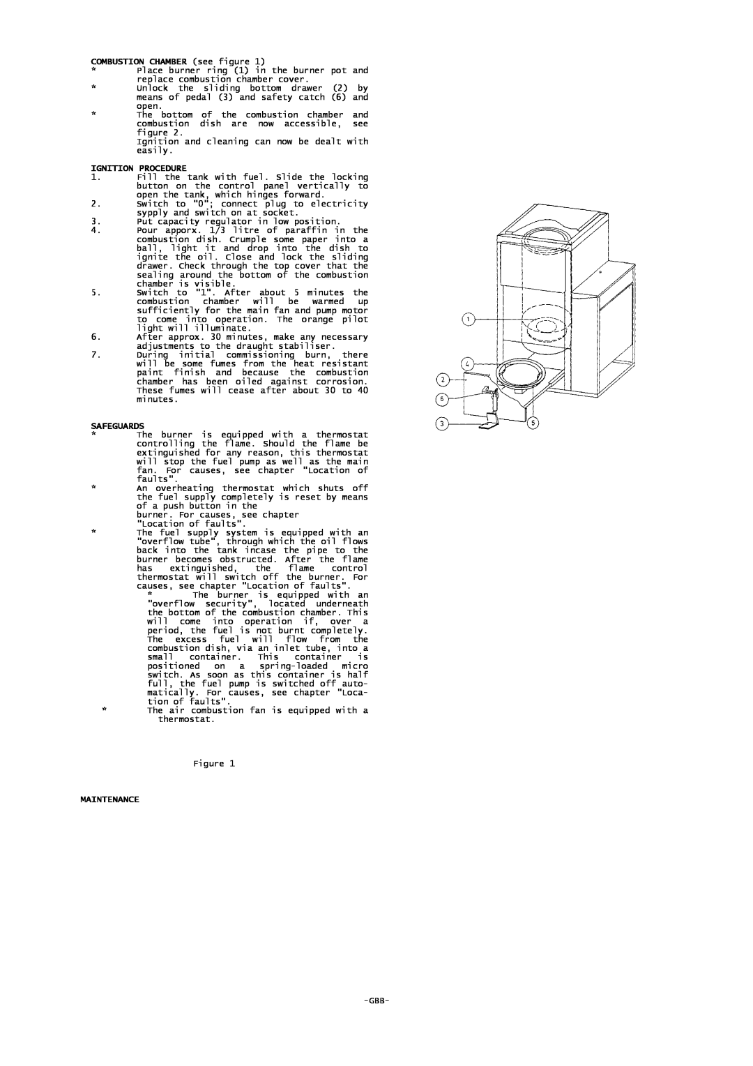
COMBUSTION CHAMBER (see figure 1)
*Place burner ring (1) in the burner pot and replace combustion chamber cover.
*Unlock the sliding bottom drawer (2) by means of pedal (3) and safety catch (6) and open.
*The bottom of the combustion chamber and combustion dish are now accessible, see figure 2.
Ignition and cleaning can now be dealt with easily.
IGNITION PROCEDURE
1.Fill the tank with fuel. Slide the locking button on the control panel vertically to open the tank, which hinges forward.
2.Switch to "0"; connect plug to electricity sypply and switch on at socket.
3.Put capacity regulator in low position.
4.Pour apporx. 1/3 litre of paraffin in the combustion dish. Crumple some paper into a ball, light it and drop into the dish to ignite the oil. Close and lock the sliding drawer. Check through the top cover that the sealing around the bottom of the combustion chamber is visible.
5.Switch to "1". After about 5 minutes the combustion chamber will be warmed up sufficiently for the main fan and pump motor to come into operation. The orange pilot light will illuminate.
6.After approx. 30 minutes, make any necessary adjustments to the draught stabiliser.
7.During initial commissioning burn, there will be some fumes from the heat resistant paint finish and because the combustion chamber has been oiled against corrosion. These fumes will cease after about 30 to 40 minutes.
SAFEGUARDS
*The burner is equipped with a thermostat controlling the flame. Should the flame be extinguished for any reason, this thermostat will stop the fuel pump as well as the main fan. For causes, see chapter "Location of faults".
*An overheating thermostat which shuts off the fuel supply completely is reset by means of a push button in the
burner. For causes, see chapter "Location of faults".
*The fuel supply system is equipped with an "overflow tube", through which the oil flows back into the tank incase the pipe to the burner becomes obstructed. After the flame has extinguished, the flame control thermostat will switch off the burner. For causes, see chapter "Location of faults".
*The burner is equipped with an "overflow security", located underneath the bottom of the combustion chamber. This will come into operation if, over a period, the fuel is not burnt completely. The excess fuel will flow from the combustion dish, via an inlet tube, into a small container. This container is positioned on a
*The air combustion fan is equipped with a thermostat.
Figure 1