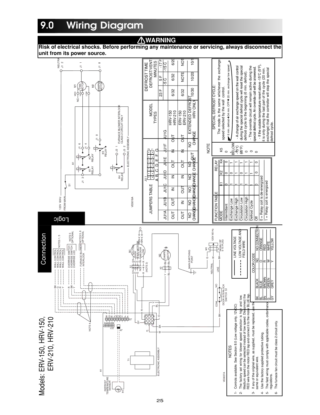
Maytag ERV-210, HRV-210, HRV-150, ERV-150 manual Wiring, Diagram

Models: ERV-150 HRV-150 ERV-210 HRV-210

1 32
Download 32 pages 21.03 Kb
Page 25
Image 25

Models: ERV-150, HRV-150, ERV-210, HRV-210


Connection


BK


WALL CONTROL


G


WALL CONTROL

NOTES 1, 5

R


WALL CONTROL

Y


WALL CONTROL


R


OVERRIDE SWITCH

NOTE 5

BK


OVERRIDE SWITCH


OPTIONAL

Y


OVERRIDE LED


NOTES 5, 6


FURNACE BLOWER


INTERLOCK


OPTIONAL

Logic

120V 60Hz


NEUTRA


J1

2

FROM MAIN


S1


A1


MED

M1


J1

6

NC

FAN


J1

HIGH

J1

1


3


MOTOR


J1

4

LOW


Risk of electrical unit from its power

9.0 Wiring

DEFROST

TEMPERATURE

SENSOR

°

t -

R1

A1

T1

NOTE 4


2 1


J4 JU1

ABCDEFG 3 4 5 6 7 8 9

I OCOLY R G B


2

F


1

F


J3


GY


4

7

J1

2 1


3


6

9


X1


M1


GY 1

GY

NEUTRAL


O

2

O

HIGH


G

3

G

FAN MOTOR


NC

BL

MEDIUM

BN

C1

R

BN


R

LOW


R


(NOTE 2)


Y


BL


K1

K2


RELAY

RELAY


M2


J1

9


DAMPER

J1 8


K5


MOTOR


RELAY


J3

1


K4


FURNACE BLOWER INTERLOCK


RELAY

J3

CLASS 2 CIRCUIT ONLY


2


ELECTRONIC ASSEMBLY


VE0018A


JU 1


DEFROST TIME


.......2


JUMPERS TABLE


MODEL


MODEL

DEFROST/VENTILATION


.......1

TYPES

MINUTES


A B C D E F G

shocks. Before performing any source.

010 !

Diagram

25

ELECTRONIC ASSEMBLY

W


BK


O


X2


M2

Y

1

BL

DAMPER

BL

2

BL

MOTOR

MAIN EARTHING

POINT


23°F

5°F

-17°F


JU1A

JU1B

JU1C

JU1D

JU1E

JU1F

JU1G


-5°C

-15°C

-27°C


OUT

OUT

IN

IN

OUT

IN

OUT

HRV-150

6/32

6/32

6/20


HRV-210


OUT

IN

OUT

IN

OUT

IN

OUT

ERV-150

6/32

NOTE

NOTE


ERV-210


NO

NO

NO

NO

NO

OUT

NO

EXTENDED DEFROST

10/30

10/20

10/15


CHANGE

CHANGE

CHANGE

CHANGE

CHANGE

CHANGE

HRV ONLY


maintenance or

WARNING

BK

VE0037A

NOTES

1- Controls available. See Section 8.0 (Low voltage only, 12VDC)

2- The factory set wiring for blower speed selection is high and low. Medium speed can be selected instead of low speed. Disconnect the RED wire from the motor RED tap and connect it to the motor BLUE tap.

3- If any of the original wire, as supplied, must be replaced, use the same or equivalent wire.

4- Use the factory supplied protective tubing.

5- The field wiring must comply with applicable codes, ordonnances and regulations.

6- The furnace fan circuit must be class 2 circuit only.


NEUTRAL


G


W1


120V 60 Hz


W


COM


NO


LINE


BK


NEMA-15P

DOOR INTERLOCK


5-15 PLUG


SWITCH S1


LINE VOLTAGE


LOW VOLTAGE AND


FIELD WIRE


COLOR CODE


BK

BLACK


NC

NO CONNECTION


BL

BLUE


O

ORANGE


BN

BROWN


R

RED


G

GREEN


W

WHITE


GY

GREY


Y

YELLOW


FUNCTION TABLE


RELAY


MODE

K1

K2

K4

K5


Intermittent

0

0

0

0


Exchange Low

1

0

1

1


Exchange High

1

1

1

1


Circulation Low

1

0

1

0


Circulation High

1

1

1

0


Defrost Cycle

1

1

1

0


Off

0

0

0

0


0 = Relay coil is de-energized

1 = Relay coil is energized

NOTE


SPECIAL DEFROST CYCLE:


The mode is the same whichever the exchange


speed selected by the wall

control.


6 min. defrost 34 min. OFF

20 min. exchange low speed

BELOW


-15°C

- A change of air exchange speed on the wall control

(-5°F)

during the special defrost cycle will reset the special


defrost cycle to the beginning (6 min. defrost).

-The override circuit will remain active during the special defrost cycle. An override call will be answered.

-If the outside temperature revert above -15°C (5°F), it is only during the last part of the cycle (20 min. exchange) that the controller will stop the special defrost cycle.

servicing, always disconnect the

Page 25
Image 25
Maytag ERV-210, HRV-210, HRV-150, ERV-150 manual Wiring, Diagram

ERV-150, HRV-150, ERV-210, HRV-210 specifications

The Maytag HRV-210, ERV-210, HRV-150, and ERV-150 are advanced heat recovery and energy recovery ventilators designed to enhance indoor air quality while promoting energy efficiency in residential settings. Each model comes packed with features tailored to balance ventilation and energy conservation, making them suitable for a variety of home environments.

The HRV-210 and HRV-150 are heat recovery ventilators that excel in transferring heat from outgoing stale air to incoming fresh air. This process effectively maintains comfortable indoor temperatures, recovering up to 70% of the heat energy, which can lead to significant energy savings during colder months. Both models boast an airflow capacity of up to 210 CFM and 150 CFM, respectively, ensuring effective ventilation for medium to large-sized homes.

On the other hand, the ERV-210 and ERV-150 embody energy recovery technology that captures not only heat but also moisture content from the air. This is particularly beneficial in humid climates where maintaining humidity levels is crucial for comfort and health. With similar airflow capacities as the HRV models, these ERVs help regulate humidity levels, preventing the growth of mold and improving indoor air quality.

All four models are equipped with energy-efficient motors designed for quiet operation, ensuring that users experience minimal noise disruption while enjoying fresh air. The inclusion of user-friendly controls and adjustable settings allows homeowners to customize their ventilation strategy according to seasonal changes or personal preferences.

Another important characteristic of the Maytag ventilators is their durable build and ease of installation. With a design that promotes straightforward maintenance, the filters can be easily accessed and cleaned or replaced, extending the life of the unit and maintaining optimal performance over time.

In addition to their functional benefits, all models adhere to industry standards for energy efficiency, contributing to sustainable living practices. The Maytag HRV-210, ERV-210, HRV-150, and ERV-150 are comprehensive solutions for homeowners looking to enhance indoor air quality while optimizing energy consumption, making them a smart investment for modern living. Each model combines innovative technologies with practical features, making them a standout choice in the realm of home ventilation systems.