6.0

Installation(cont’d)

6.3PLANNING OF THE DUCTWORK

a)Follow the instructions in Section 6.4 below to determine the appropriate duct diameters for your system.

b)Keep it simple. Plan for a minimum number of bends and joints. Keep the length of insulated duct to a minimum.

c)Do not use wall cavities as ducts. Do not use branch lines smaller than 4” (102 mm) Ø.

d)Do not ventilate crawl spaces or cold rooms. Do not attempt to recover the exhaust air from a dryer or a range hood. This would cause clogging of the recovery module. Use sheet metal for the kitchen exhaust duct.

e)Be sure to plan for at least one exhaust register on the highest lived-in level of the house if it has 2 floors or more.

6.4CALCULATING THE DUCT SIZE

Use the table below to ensure that the ducts you intend to install will be carrying air flows at or under the recommended values. Avoid installing ducts that will have to carry air flows near the maximum values and never install a duct if its air flow exceeds the maximum value.


Duct

Recommended

Maximum


Diameter

Air Flow


Air Flow


4”(102 mm)

40 cfm

19 l/s

68 m3/h

60 cfm

28 l/s

102 m3/h


5”(127 mm)

75 cfm

35 l/s

127 m3/h

110 cfm

52 l/s

187 m3/h


6”(152 mm)

120 cfm

57 l/s

204 m3/h

180 cfm

85 l/s

306 m3/h


7”(178 mm)

185 cfm

87 l/s

314 m3/h

270 cfm

127 l/s

459 m3/h


8”(203 mm)

260 cfm

123 l/s

442 m3/h

380 cfm

179 l/s

645 m3/h

NOTE: Examples 6.4.1 and 6.4.2 use imperial measures. The same calculation applies to metric measures.

end branches

5”ø

70 cfm

main branch 6”ø 140 cfm

140 cfm

VI0003

figure 8

6.4.1Example of calculation:

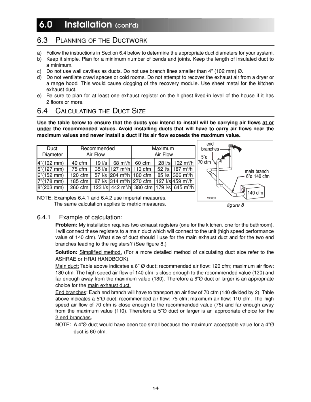
Problem: My installation requires two exhaust registers (one for the kitchen, one for the bathroom). I will connect these registers to a main duct which will connect to the unit (high speed performance value of 140 cfm). What size of duct should I use for the main exhaust duct and for the two end branches leading to the registers? (See figure 8.)

Solution: Simplified method. (For a more detailed method of calculating duct size refer to the ASHRAE or HRAI HANDBOOK).

Main duct: Table above indicates a 6” Ø duct: recommended air flow: 120 cfm; maximum air flow: 180 cfm. The high speed air flow of 140 cfm is close enough to the recommended value (120) and far enough away from the maximum value (180). Therefore a 6”Ø duct or larger is an appropriate choice for the main exhaust duct.

End branches: Each end branch will have to transport an air flow of 70 cfm (140 divided by 2). Table

above indicates a 5ӯ duct: recommended air flow: 75 cfm; maximum air flow: 110 cfm. The high speed air flow of 70 cfm is close enough to the recommended value (75) and far enough away from the maximum value (110). Therefore a 5ӯ duct or larger is an appropriate choice for the 2 end branches.

NOTE: A 4ӯ duct would have been too small because the maximum acceptable value for a 4ӯ duct is 60 cfm.

14

Page 14
Image 14
Maytag HRV-150, HRV-210, ERV-210, ERV-150 manual Installation cont’d, Planning of the Ductwork, Calculating the Duct Size

ERV-150, HRV-150, ERV-210, HRV-210 specifications

The Maytag HRV-210, ERV-210, HRV-150, and ERV-150 are advanced heat recovery and energy recovery ventilators designed to enhance indoor air quality while promoting energy efficiency in residential settings. Each model comes packed with features tailored to balance ventilation and energy conservation, making them suitable for a variety of home environments.

The HRV-210 and HRV-150 are heat recovery ventilators that excel in transferring heat from outgoing stale air to incoming fresh air. This process effectively maintains comfortable indoor temperatures, recovering up to 70% of the heat energy, which can lead to significant energy savings during colder months. Both models boast an airflow capacity of up to 210 CFM and 150 CFM, respectively, ensuring effective ventilation for medium to large-sized homes.

On the other hand, the ERV-210 and ERV-150 embody energy recovery technology that captures not only heat but also moisture content from the air. This is particularly beneficial in humid climates where maintaining humidity levels is crucial for comfort and health. With similar airflow capacities as the HRV models, these ERVs help regulate humidity levels, preventing the growth of mold and improving indoor air quality.

All four models are equipped with energy-efficient motors designed for quiet operation, ensuring that users experience minimal noise disruption while enjoying fresh air. The inclusion of user-friendly controls and adjustable settings allows homeowners to customize their ventilation strategy according to seasonal changes or personal preferences.

Another important characteristic of the Maytag ventilators is their durable build and ease of installation. With a design that promotes straightforward maintenance, the filters can be easily accessed and cleaned or replaced, extending the life of the unit and maintaining optimal performance over time.

In addition to their functional benefits, all models adhere to industry standards for energy efficiency, contributing to sustainable living practices. The Maytag HRV-210, ERV-210, HRV-150, and ERV-150 are comprehensive solutions for homeowners looking to enhance indoor air quality while optimizing energy consumption, making them a smart investment for modern living. Each model combines innovative technologies with practical features, making them a standout choice in the realm of home ventilation systems.