Installation for Wall Stud at One End Hole (Figure 3)

1.Drill a 3/16" (5 mm) hole into the wall stud at the end hole marked in Step 3 of “Mark Rear Wall.”

2.If installing on a second wall stud, drill a 3/16" (5 mm) hole into the wall stud at the other hole marked in Step 6 of “Mark Rear Wall.” Refer to Figure 3 in “Possible Wall Stud Configurations” in “Locate Wall Stud(s)” section.

3.Drill a 3/4" (19 mm) hole through the wall at the other end hole.

Installation for Wall Studs at Both End Holes (Figure 4)

Drill 3/16" (5 mm) holes into the studs at the end holes marked in Step 3 of “Mark Rear Wall.”

Attach Mounting Plate to Wall

NOTE: Secure the mounting plate to the wall at both end holes drilled into the wall studs and/or drywall using either 1/4-20 x 3" round-head bolts and toggle nuts or 1/4 x 2" lag screws.

Refer to illustrations in “Possible Wall Stud Configurations” in “Locate Wall Stud(s)” section.

No Wall Studs at End Holes (Figures 1 & 2)

NOTE: The mounting plate must be secured to the wall on at least 1 wall stud as well as at both ends.

1.With the support tabs of the mounting plate facing forward, insert 1/4-20 x 3" round-head bolts through both end holes of mounting plate.

2.Start toggle nuts on bolts from the back of the mounting plate. Leave enough space for the toggle nuts to go through the wall and to open.

B

A

C

A. 1/4-20 x 3" round-head bolt

B. Mounting plate

C. Spring toggle nut

3.Position mounting plate on the wall.

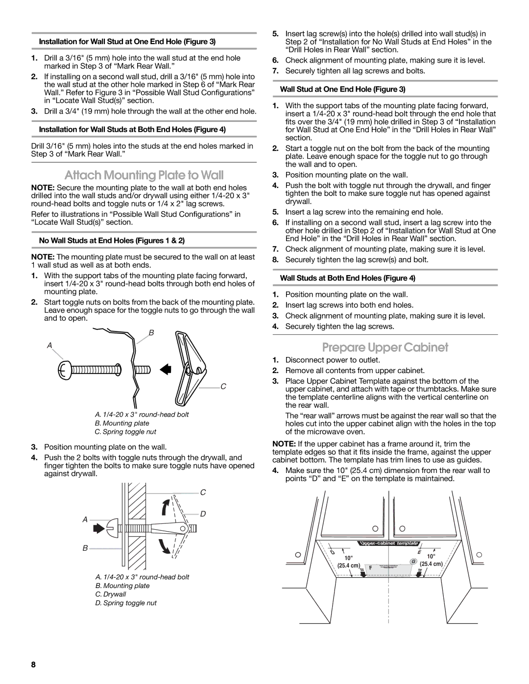
4.Push the 2 bolts with toggle nuts through the drywall, and finger tighten the bolts to make sure toggle nuts have opened against drywall.

C

D

A

B

A. 1/4-20 x 3" round-head bolt

B. Mounting plate

C.Drywall

D.Spring toggle nut

5.Insert lag screw(s) into the hole(s) drilled into wall stud(s) in Step 2 of “Installation for No Wall Studs at End Holes” in the “Drill Holes in Rear Wall” section.

6.Check alignment of mounting plate, making sure it is level.

7.Securely tighten all lag screws and bolts.

Wall Stud at One End Hole (Figure 3)

1.With the support tabs of the mounting plate facing forward, insert a 1/4-20 x 3" round-head bolt through the end hole that fits over the 3/4" (19 mm) hole drilled in Step 3 of “Installation for Wall Stud at One End Hole” in the “Drill Holes in Rear Wall” section.

2.Start a toggle nut on the bolt from the back of the mounting plate. Leave enough space for the toggle nut to go through the wall and to open.

3.Position mounting plate on the wall.

4.Push the bolt with toggle nut through the drywall, and finger tighten the bolt to make sure toggle nut has opened against drywall.

5.Insert a lag screw into the remaining end hole.

6.If installing on a second wall stud, insert a lag screw into the other hole drilled in Step 2 of “Installation for Wall Stud at One End Hole” in the “Drill Holes in Rear Wall” section.

7.Check alignment of mounting plate, making sure it is level.

8.Securely tighten the lag screw(s) and bolt.

Wall Studs at Both End Holes (Figure 4)

1.Position mounting plate on the wall.

2.Insert lag screws into both end holes.

3.Check alignment of mounting plate, making sure it is level.

4.Securely tighten the lag screws.

Prepare Upper Cabinet

1.Disconnect power to outlet.

2.Remove all contents from upper cabinet.

3.Place Upper Cabinet Template against the bottom of the upper cabinet, and attach with tape or thumbtacks. Make sure the template centerline aligns with the vertical centerline on the rear wall.

The “rear wall” arrows must be against the rear wall so that the holes cut into the upper cabinet align with the holes in the top of the microwave oven.

NOTE: If the upper cabinet has a frame around it, trim the template edges so that it fits inside the frame, against the upper cabinet bottom. The template has trim lines to use as guides.

4.Make sure the 10" (25.4 cm) dimension from the rear wall to points “D” and “E” on the template is maintained.

Upper-cabinet template


D


E

10"

G

10"

(25.4 cm)

(25.4 cm)


F


8

Page 8
Image 8
Maytag W10191953A installation instructions Attach Mounting Plate to Wall, Prepare Upper Cabinet

W10191953A specifications

The Maytag W10191953A is a notable appliance part designed to enhance the performance and efficiency of Maytag washing machines. As a quality component, it reflects Maytag's commitment to robust manufacturing and reliability. This part is primarily recognized as a washing machine door strike, playing an essential role in ensuring the proper sealing and functioning of the washer door.

One of the main features of the W10191953A is its durable construction. Made from high-quality materials, the door strike is designed to withstand the rigors of regular use, ensuring longevity and reducing the likelihood of failure. This robustness is crucial in maintaining the operational integrity of the washing machine, preventing leaks, and ensuring that the door remains securely closed during cycles.

In terms of technology, the W10191953A is engineered for compatibility with a variety of Maytag front-load and top-load washing machines. This versatility makes it an essential replacement part for users looking to maintain their appliance’s optimal performance. The installation of this door strike is straightforward and can often be completed without professional assistance, making it accessible for DIY enthusiasts and homeowners.

The W10191953A also features a precise design that ensures an exact fit, which is essential in maintaining the washer's efficiency. When the door strike is working correctly, it facilitates the activation of safety mechanisms within the washing machine, ensuring that cycles cannot start until the door is correctly secured. This not only enhances user safety but also protects the appliance from potential damage.

Another characteristic of the W10191953A is its ability to reduce operational noise. A properly functioning door strike minimizes the rattling and vibrations that can occur during a wash cycle, leading to a quieter laundry experience. This aspect is particularly valued in households where the washing machine is located near living areas.

In summary, the Maytag W10191953A is an essential component that embodies the quality and reliability of Maytag appliances. With its durable construction, compatibility with various models, ease of installation, safety features, and noise-reducing capabilities, it stands out as a vital part for ensuring optimal washing machine performance. For anyone looking to maintain their Maytag washer, the W10191953A is an excellent choice that promises to deliver lasting benefits.