3.Use a drywall saw or other appropriate tool to carefully cut out the speaker holes. The
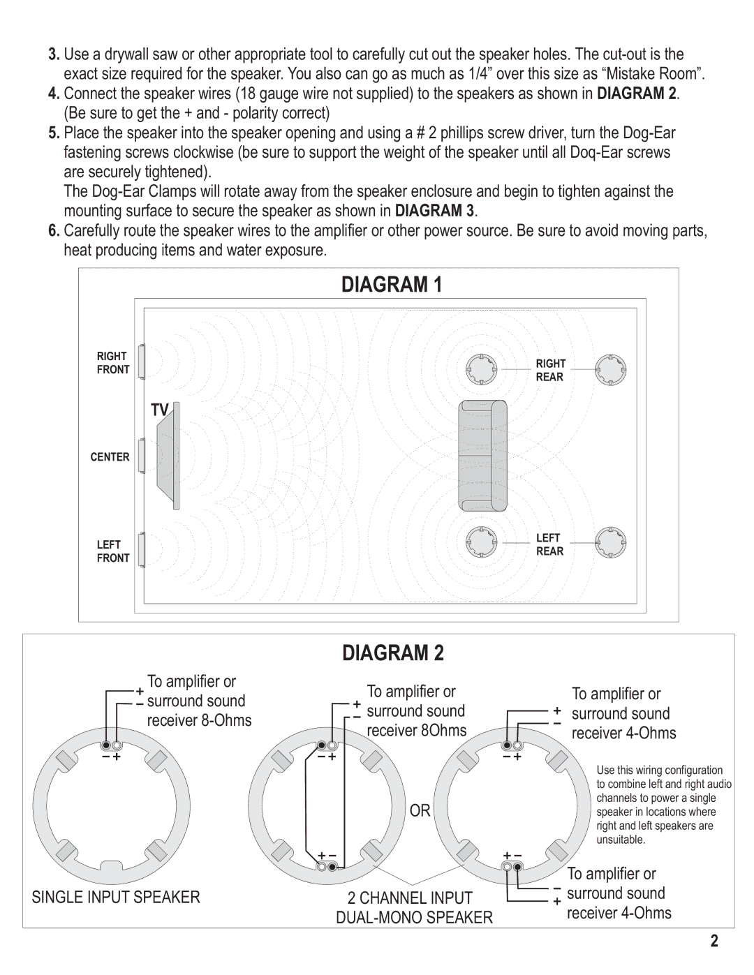
4.Connect the speaker wires (18 gauge wire not supplied) to the speakers as shown in DIAGRAM 2. (Be sure to get the + and - polarity correct)
5.Place the speaker into the speaker opening and using a # 2 phillips screw driver, turn the
The
6.Carefully route the speaker wires to the amplifier or other power source. Be sure to avoid moving parts, heat producing items and water exposure.
| DIAGRAM 1 | |
RIGHT | RIGHT | |
FRONT | ||
REAR | ||
| ||
| TV | |
CENTER |
| |
LEFT | LEFT | |
REAR | ||
FRONT | ||
|
To amplifier or surround sound receiver
SINGLE INPUT SPEAKER
DIAGRAM 2
To amplifier or surround sound receiver 8Ohms
OR
2 CHANNEL INPUT DUAL-MONO SPEAKER
To amplifier or surround sound receiver 4-Ohms
Use this wiring configuration to combine left and right audio channels to power a single speaker in locations where right and left speakers are unsuitable.
To amplifier or surround sound receiver
2