Manuals
/
Lennox International Inc
/
Household Appliance
/
Furnace
Lennox International Inc
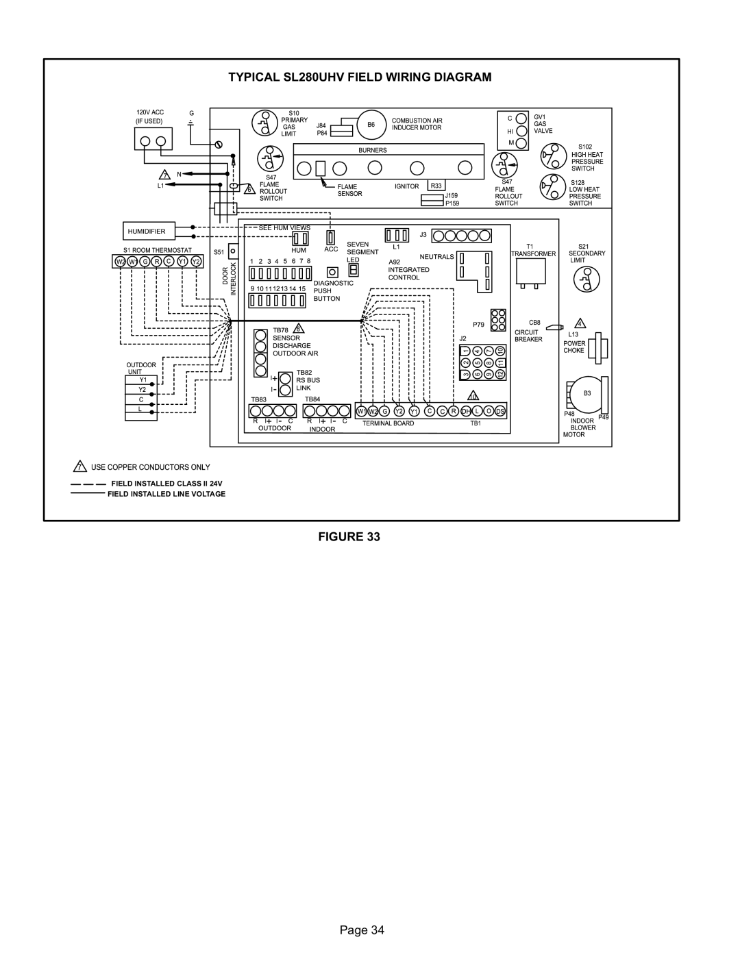
SL280UH090V36B, SL280UH090V48B Typical SL280UHV Field Wiring Diagram
Models:
SL280UH090V36B
SL280UH070V36A
DAVE LENNOX SIGNATURE COLLECTION GAS FURNACE UPFLOW / HORIZONTAL AIR DISCHARGE
SL280UH090V48B
1
34
72
72
Download
72 pages
31.79 Kb
31
32
33
34
35
36
37
38
Repair Parts List
GAS Meter Clocking Chart
Fault is cleared
Communicating System Wiring
Dimension
Soft lockout or reset
Vent Connector
Access Panel Blower Assembly
Other Unit Adjustments
Setting Equipment
Page 34
Image 34
TYPICAL SL280UHV FIELD WIRING DIAGRAM
FIELD INSTALLED CLASS II 24V
FIELD INSTALLED LINE VOLTAGE
FIGURE 33
Page 34
Page 33
Page 35
Page 34
Image 34
Page 33
Page 35
Contents
Installation Instructions SL280UHV
Table of Contents
Side Return Air Opening
Unit Dimensions − inches mm
Return air from both sides
Either Side
Parts Arrangement
Access Panel Blower Assembly
Sight Glass
SL280UHV Gas Furnace
Safety Information
Shipping and Packing List
Air Handler Unit
Use of Furnace as Construction Heater
General
Evaporator
Combustion, Dilution & Ventilation Air
Equipment in Confined
Space ALL AIR from Inside
Equipment in Confined Space
Equipment in Confined Space ALL AIR from Outside
Equipment Confined Space ALL AIR from Outside
Bottom
Setting Equipment
Blower Motor Rigid LEG
Indoor AIR
20 X 25 X
Furnace Front
Return AIR Base
End Bottom
Horizontal Application Installation Clearances Top Left
Right
Typical Horizontal Application
Filters
Duct System
Top Vent Discharge
Venting
Upflow Position
Left Side Vent Discharge
Horizontal Right Position
Horizontal Left Position
Side Vent Discharge
Sticker
Common Venting Using Metal−Lined Masonry Chimney
Disconnected Vent
Vent Pipe
Vent Connector
Through an unused masonry chimney flue is not considered
102 127 −1/2 152 178 10−1/2
MIN MAX
Feet
FAN + FAN FAN + NAT
130
Carbon Monoxide Poisoning Hazard
Gas Piping
Ers or straps. Install a drip leg in vertical pipe runs to
− In some localities, codes may require the installation
Every 8 to 10 feet 2.44 to 3.01 m with suitable hang
Left−Side Air Discharge
Horizontal Application
Right−Side Air Discharge
Electrostatic Discharge ESD
Interior MAKE−UP BOX Installation
Electrical
BOX
Non−Communicating
Communicating
Icomfortt Integrated Control Outdoor Unit Icomfort Touch
120V Connections
NON−COMMUNICATING System Wiring
Communicating System Wiring
Applications
DIP Switch Settings and On−Board Links See figure
OFF
Single Stage
Thermostat w Dual fuel capa Bilities
SL280UHV Schematic Wiring Diagram
Typical SL280UHV Field Wiring Diagram
RS−BUS Link TB82, future use
Integrated Control
+ = Data High Connection − = Data LOW Connection
−10% approx
OFF
On−Board Links
940
1045
985
880
SL280UH090V36B Blower Performance less filter
1155
1280
1220
1095
1170
1295
1235
1110
1165
1360
1230
1100
1160
1290
1225
1380
+18% 1605
SL280UH110V60C Blower Performance less filter
+18% 1785
SL280UH135V60D Blower Performance less filter
Operating Sequence
Compressor
Thermostat energizes Y2
White Rodgers GAS Valve
For Your Safety Read Before Lighting
Unit Start−Up
Honeywell GAS Valve
Proper Combustion
Gas Pressure Adjustment
GAS Meter Clocking Chart
Dial
High Altitude
Other Unit Adjustments
Heating Sequence of Operation
Heating Operation with Single Stage Thermostat
Heating Operation with TWO−STAGE Thermostat
SEC
Service
Electrical SHOCK, Fire Or Explosion Hazard
11− Back wash using steam. Begin from the burner opening
SL280UHV BURNER, Combustion AIR Inducer Assembly
13− To clean the combustion air inducer visually inspect
17− Reinstall burner box, manifold assembly and burner box
SL280UHV NOX Inserts
Planned Service
Repair Parts List
Integrated Control Diagnostic Modes
Integrated Control Diagnostic Codes
Power at the thermostat. Alert stops all services
Normal operation 5 seconds after fault recovered
Furnace / air handler. Clears after fault recovered
Equipment is unable to communicate. Indicates
Control will still operate on default parameter set
Reconfigure the system. Replace control if heating
Missioning and Execute ’Set Factory Default mode’
Ate feature will be set as ’installed’ and that could
Fault is cleared
Low pressure switch failed open
Sumes normal operation after fault is cleared
Tion after fault is cleared
Soft lockout or reset
Open or not within specifications −hour soft lock
Out. Clears when flame has been proven stable
To flame failure
Error after current is sensed in both RUN
Pair/add duct. Cleared after the current service de
Is not running. Check power to outdoor unit. Clears
Vice is removed, or after power reset
Sor run cycle, or after power reset
Program Unit Capacity/Size Mode
Finished
Troubleshooting Heating Sequence of Operation
Call for FIRST−STAGE Heat
Call for SECOND−STAGE Heat
Call for Heat Satisfied
Call for Heat Satisfied FIRST−STAGE Heat SECOND−STAGE Heat
2ND Stage Heat
Troubleshooting Cooling Sequence of Operation
Call for Cooling
Troubleshooting Continuous Fan Sequence of Operation
Call for FAN
Top
Page
Image
Contents