
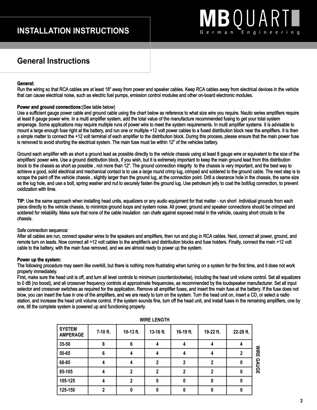
NAU460, NAU660, NAU260 specifications
MB Quart has long been synonymous with high-performance audio systems, and their NAU series—specifically, the NAU660, NAU460, and NAU260—continues this legacy. Each model in the NAU series is engineered to provide superior sound quality and robust performance, making them ideal choices for car audio enthusiasts and home audio applications alike.The NAU660 is the flagship model of the series, featuring a powerful power output of 600 watts. This model is designed to deliver crystal-clear sound across a wide frequency range, ensuring that every note and beat is faithfully reproduced. The NAU660 includes advanced Class D amplification technology, which not only enhances sound efficiency but also reduces heat generation, leading to increased longevity of the unit.
Next in line is the NAU460, which offers a balance between performance and affordability. With a power output of 400 watts, this model doesn't compromise on sound quality. It features high-quality components, including custom-engineered driver elements designed to deliver deep bass and clear highs. The NAU460 is particularly suitable for users looking to upgrade their factory audio systems without breaking the bank.
Lastly, the NAU260 is a versatile model that caters to compact car audio setups. With a power output of 260 watts, it is designed for urban drivers who want a quality audio experience without the bulk. Despite its smaller size, the NAU260 boasts impressive sound reproduction with enhanced bass response, making it perfect for modern music genres.
All three models feature user-friendly controls, allowing for easy adjustments to suit individual listening preferences. The sleek design ensures that they seamlessly integrate into any audio setup, whether in a vehicle or a home theater system. Additionally, these models incorporate various protection circuits to safeguard against overheating and short circuits, ensuring safe operation during extensive use.
The MB Quart NAU series is equipped with high-pass and low-pass crossover technologies, enabling users to optimize frequency output based on speaker configurations. This feature enhances the overall audio experience, ensuring that the right frequencies reach the right speakers.
In summary, the MB Quart NAU660, NAU460, and NAU260 each deliver impressive audio performance, tailored to meet the varying needs of audio enthusiasts. With advanced technology and robust design, these models exemplify MB Quart's commitment to innovation in sound quality. Whether for everyday use or a high-performance system, the NAU series stands out as a reliable choice.