115154526, 433B, 952715746 specifications
The McCulloch 952715746,433B,115154526 is a robust and versatile outdoor power tool designed for both professional landscapers and homeowners focused on achieving precision in their yard care tasks. This model combines durability with advanced technology to provide excellent performance across various applications.One of the standout features of the McCulloch 952715746 is its powerful engine, which delivers impressive power output and ensures efficient operation. The engine is designed to handle the toughest tasks, whether it's trimming hedges, cutting branches, or clearing brush. In particular, the optimal displacement ensures that users can work for extended periods without facing overheating or stalling issues, providing reliable performance throughout extended use.
The ergonomic design of the McCulloch 952715746 also enhances usability. Its lightweight construction makes it easy to maneuver, reducing fatigue during extended use. The integrated safety features, including a reliable throttle trigger and a comfortable grip, further enhance user safety and comfort during operation. This model was built with user-friendliness in mind, making it accessible for users of all skill levels.
In terms of technology, the McCulloch 952715746 incorporates advanced fuel-efficient systems. These technologies not only reduce emissions but also optimize fuel consumption, allowing users to work longer while saving on fuel costs. Furthermore, the easy-start mechanism simplifies the starting process, ensuring that users can get to work quickly.
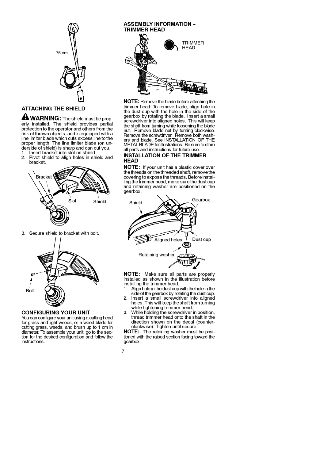
Another key characteristic of this model is its versatility. It comes with interchangeable attachments that allow it to adapt to various tasks, making it a practical choice for users who need a multi-functional tool. Whether cutting, trimming, or edging, the McCulloch 952715746 proves to be a reliable companion.
In summary, the McCulloch 952715746,433B,115154526 combines power, efficiency, and versatility in one package. Its advanced technology, along with its lightweight and ergonomic design, makes it an excellent choice for anyone looking to enhance their outdoor maintenance capabilities. With the ability to tackle a wide range of tasks, this model stands out as a valuable tool in any lawn care arsenal. Whether you are a seasoned professional or a casual gardener, the McCulloch 952715746 is sure to meet and exceed your expectations in performance and reliability.

