Technical Description
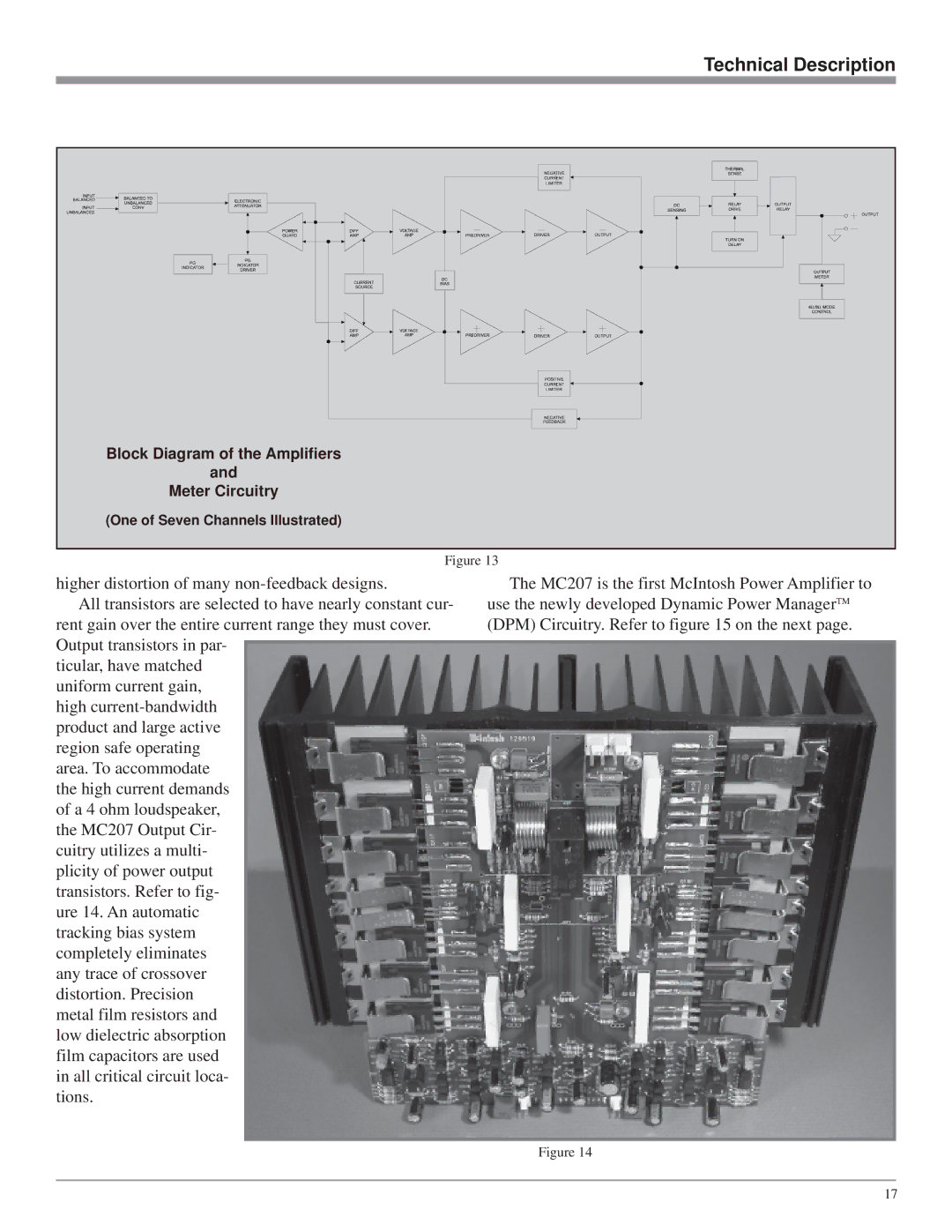
Block Diagram of the Amplifiers |
and |
Meter Circuitry |
(One of Seven Channels Illustrated) |
Figure 13
higher distortion of many
All transistors are selected to have nearly constant cur- rent gain over the entire current range they must cover. Output transistors in par-
ticular, have matched uniform current gain, high
The MC207 is the first McIntosh Power Amplifier to use the newly developed Dynamic Power ManagerTM (DPM) Circuitry. Refer to figure 15 on the next page.
Figure 14
17